
I have always had a fascination with classic cars. They are fun to admire, drive and work on, but sometimes they lack the comfort of modern cars. Driving a car without air conditioning in the hot summer months has led me to test many window configurations to maintain a cool internal temperature without getting windburn on your face. I have decided to use SOLIDWORKS Flow Simulation to put my window configuration hypothesis to the test.
SOLIDWORKS Flow Simulation is a computational fluid dynamics tool that can be added into your SOLIDWORKS environment, and can calculate product performance. In SOLIDWORKS Flow Simulation, I am going to run a parametric simulation where the windows are open different amounts to see which configuration will cool the car off the fastest while not being uncomfortable for the driver.
Model Preparation
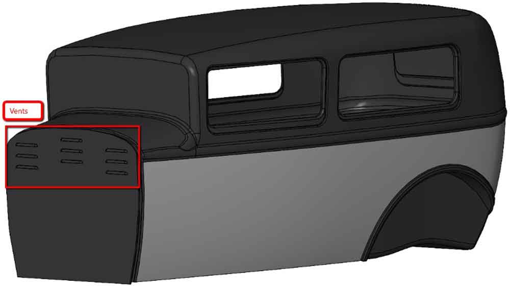
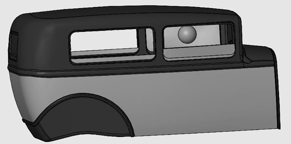
To start, I had to prepare the model for flow simulation. This meant removing any minute details and ensuring the SOLIDWORKS model was watertight. In my model, I had to close off the small vents in the front of the car and some internal cavities. After making the appropriate modifications to the model, the check tool can be used to verify if the model is usable in flow simulation.
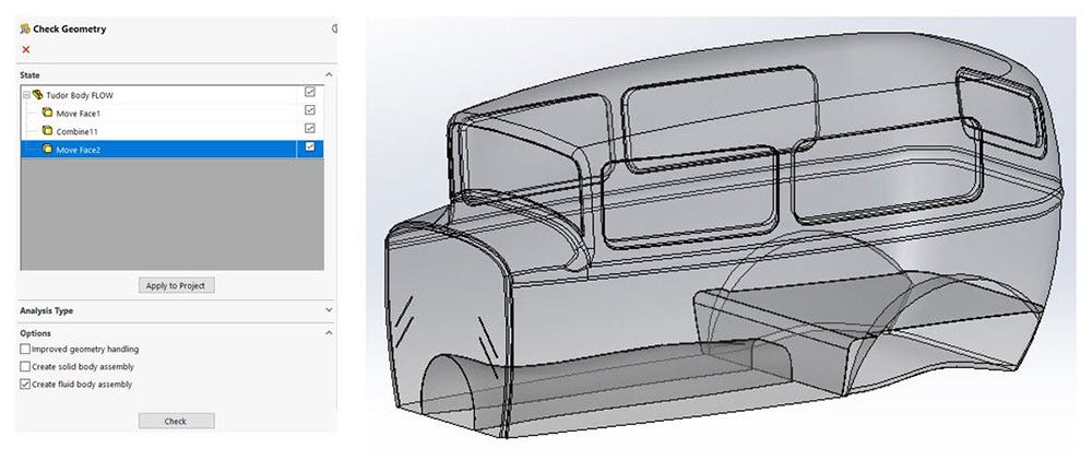
This check tool also has another great feature. You can create a solid body of the fluid volume and use that to generate a custom mesh, set initial fluid conditions in that volume, and create a target goal. Using a configuration of the car with closed windows, I used the check tool to create a solid body of the internal volume of the car to be used in the pre and post-processing of the simulation. With the appropriate box checked, a new file is created from the vacant space inside the model.
Now it was time to set up my simulation. Before jumping headfirst into the software, there were a few key questions I wanted to be answered and those questions drove the setup of the study itself.
Simulation Setup
The questions I want to answer in the simulation include:
- How long does it take to cool the car down to a stable temperature with the windows open traveling at 100km/hr?
- What is the wind force on the driver’s head?
- an I figure out the ideal window configuration to keep the air circulating through the vehicle to reduce the internal temperature without applying an uncomfortable wind load to the driver?
These questions are going to drive certain settings and properties of the study.
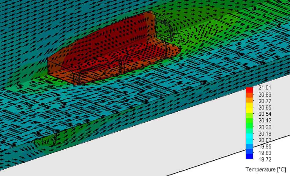
Since I want to know the time it takes to cool down the cab of the car, I must run a time-dependent study. To simulate a wind tunnel-like environment, I will set the ambient fluid velocity to the desired vehicle speed. A goal will be set for the force on the driver’s head and another for the bulk ambient temperature of the fluid volume inside the vehicle. A parametric study will be used to change the window configuration by manipulating a dimension. This parametric study will run a series of simulations with different dimension values and display the goal parameters.
Now that I know what I want from my simulation and the options and parameters I need to set up, let’s look at the process.
Simulation Process
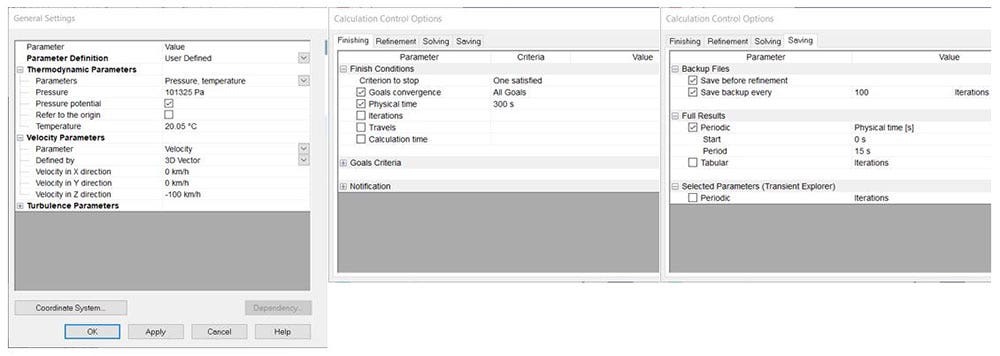
To simulate the car driving at a constant speed, the ambient fluid conditions are set to have a velocity of 100 km/hr. This is done in the general settings under the initial conditions tab. On the Analysis Type tab, the time-dependent box should be checked on so results can be viewed at different physical time steps.
In the calculation control options menu, you can set the finishing conditions, which specify when to stop running the simulation. Using the criteria to stop check boxes, the simulation will stop after the goals have converged or 300 s (five min) of physical time has passed. Since the simulation is time-dependent, the saving conditions need to be set so you can view results at certain time steps. The saving conditions are set in the calculation control options on the saving tab. Using the periodic physical time steps of 15 seconds will save full flow results every 15 seconds.
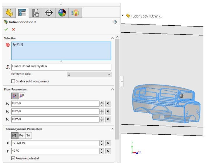
Next, set the initial conditions for the air inside of the vehicle. This is where the fluid body created with the check tool comes into play. Using the initial conditions tool, set the flow parameters to 0 velocity inside the vehicle and the thermodynamic parameters to an initial temperature of 40°C.
The goal for the simulation is to stabilize the temperature of the internal volume and the air force applied to the sphere representing the driver’s head. These goals are used for convergence of the study and easy viewing of the values. To stabilize the temperature of the internal volume, a bulk average temperature goal needs to be set on the fluid volume body. To understand the wind force on the driver’s head, create a surface goal on the sphere body representing the head.

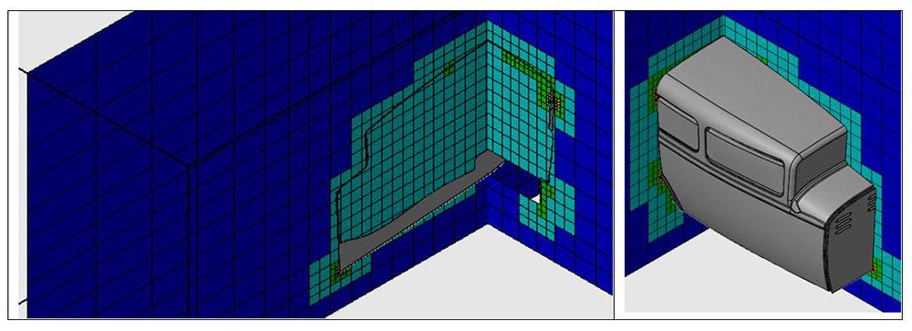
After all those conditions are set, it is time to look at the mesh. A manual mesh will be used to generate the basic mesh with some channel refinement to catch the gap in the windows. A local mesh can be added to the internal fluid volume body and the surfaces surrounding the window openings. The global mesh will keep the elements outside the fluid body at the prescribed size and the local mesh will increase the resolution in the areas of interest, the window openings and internal fluid, as seen in the image below.
Results of the Study
At this stage, it is best to run the simulation to ensure it solves and no mistakes were made in the setup. The results of interest are the time it takes to stabilize the internal temperature and the force on the driver’s head. Both of those numbers are obtained from creating a goal plot. My hypothesized ideal situation cooled the car down from 40°C to 21°C in about 80 seconds only distributing 0.002 lbs of force on the driver. The simulation solves and the results are realistic, so it is time to set up the parametric study.
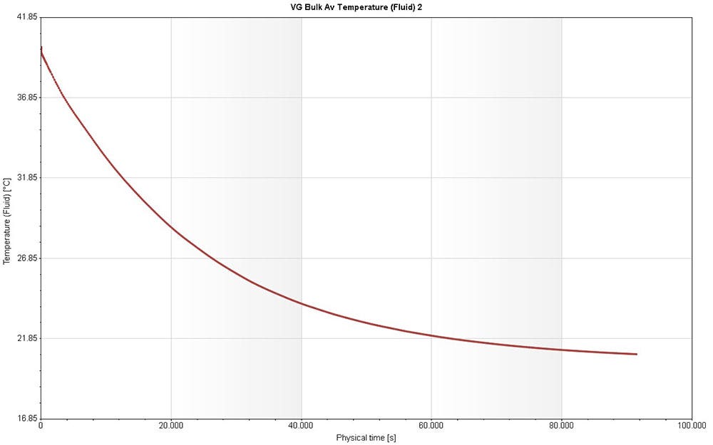
This is a goal plot produced by SOLIDWORKS Flow Simulation showing the time it takes to cool the interior temperature of the vehicle.
Parametric Study
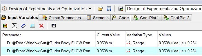
A Design of Experiments and Optimization study will be the type of Parametric Study to use. This will allow me to vary multiple input variables to create different simulation scenarios. The dimensions controlling the amount of window opening will be set to range from two inches to 10 inches.
The experiments are created in the scenario tab using the find optimum criteria to minimize the two goals. Setting the number of experiments input box to 35 will yield a good understanding of how the input variables affect the goals. After running the time-dependent experiments, a lot of data is generated but SOLIDWORKS Flow Simulation allows for easy export into excel. Excel can easily filter out the experiments that put too high of a wind load on the head and view the desired data in table, summary or graph format. Below is a graphical representation of the temperature and time results of the studies that have an acceptable wind force.
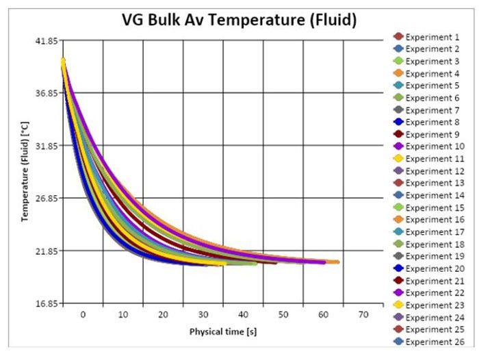
Sifting through the data further the best window configuration, of the simulated configurations, was found to have a wind force of 0.003 lbs, minimum temperature of 20.51°C and only took 23 s to obtain a temperature below 21°C. This ideal configuration had the driver’s front window fully closed, the front passenger window opened about eight inches, and the two rear windows opened 10 in.
Future Considerations
To better improve this experiment, I would like to fully model the interior of the vehicle to see how that change of geometry affects the flow. I would also like to simulate slower driving speeds and hotter interior temperatures to understand how those variables would affect the results. Adding an initial temperature to the interior surfaces could also improve the realism of the study. Leave a comment if you would like to see this simulation pushed further.
Visit our website for more information on SOLIDWORKS Flow Simulation and if you have any questions, please contact us at Hawk Ridge Systems today. Thanks for reading!


