In this two-part blog series, we will review customizing a Title Block in SOLIDWORKS Electrical. While the default library comes with some standard title blocks in various sizes, you will likely want to customize the default title blocks or import legacy title blocks.
The first part of this series will cover general recommendations for title block management, an overview of the Status Bar and Drawing Parameters, and tips and tricks regarding borders and logos. The second blog in the series, “SOLIDWORKS Electrical Title Block Tips You Should Know: Part Two” focuses on attributes management along with setting up rows and columns, as well as some closing recommendations.
General Recommendations
The process of importing legacy title blogs in DWG or DXF format is covered in the blog, “SOLIDWORKS Electrical: Importing Title Blocks.” You will need to ensure that the title blocks are in model space before the import.
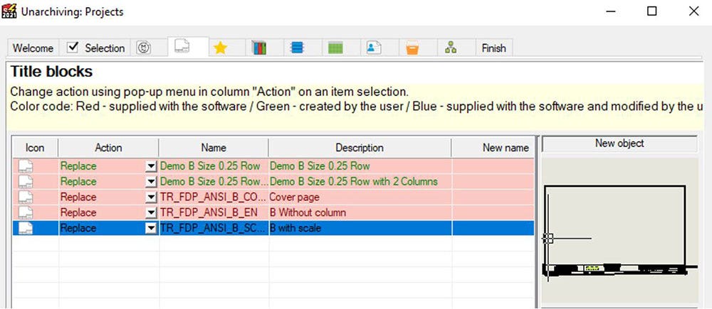
If you plan to modify a default title block, we strongly recommend against it but instead create a copy of it to customize. The reason for this is that title blocks and symbols are DWG files stored in the Electrical data folder. When upgrading SOLIDWORKS Electrical to a new major version or service pack, the first user to launch the software will be prompted with the Data Update wizard. This will refresh your libraries with all the defaults and if you aren’t careful, you might overwrite a modified default title block with its original version since both DWGs have the same filename. This might also occur if you were to run the Data Update wizard while unarchiving an older project.
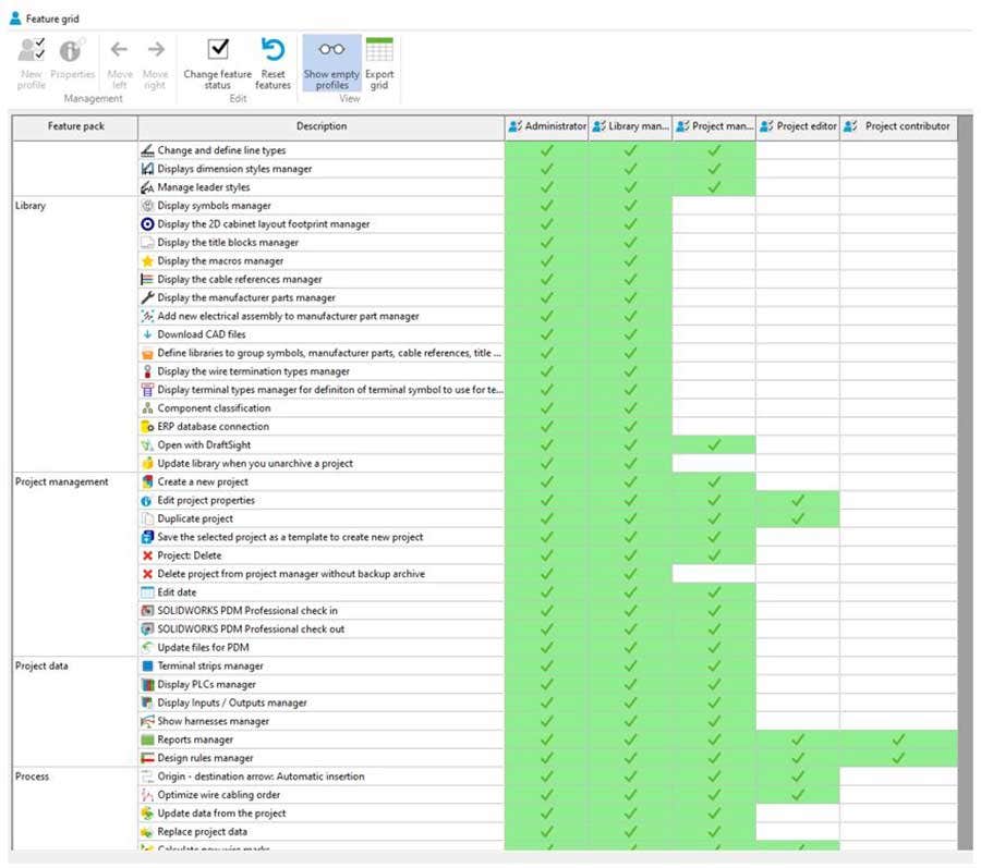
The best way to safeguard against this is to leave the default title blocks and symbols alone and instead create copies, rename and edit them. The modified copies will be exempt from being overwritten. You might also consider leveraging the built-in User Rights Management capabilities (TOOLS > INTERFACE CONFIGURATION > RIGHTS MANAGEMENT) to restrict library modifications to approved users. One of the enhancements in SOLIDWORKS Electrical 2020 was the ability to create a customized user profile with an editable Feature Grid.
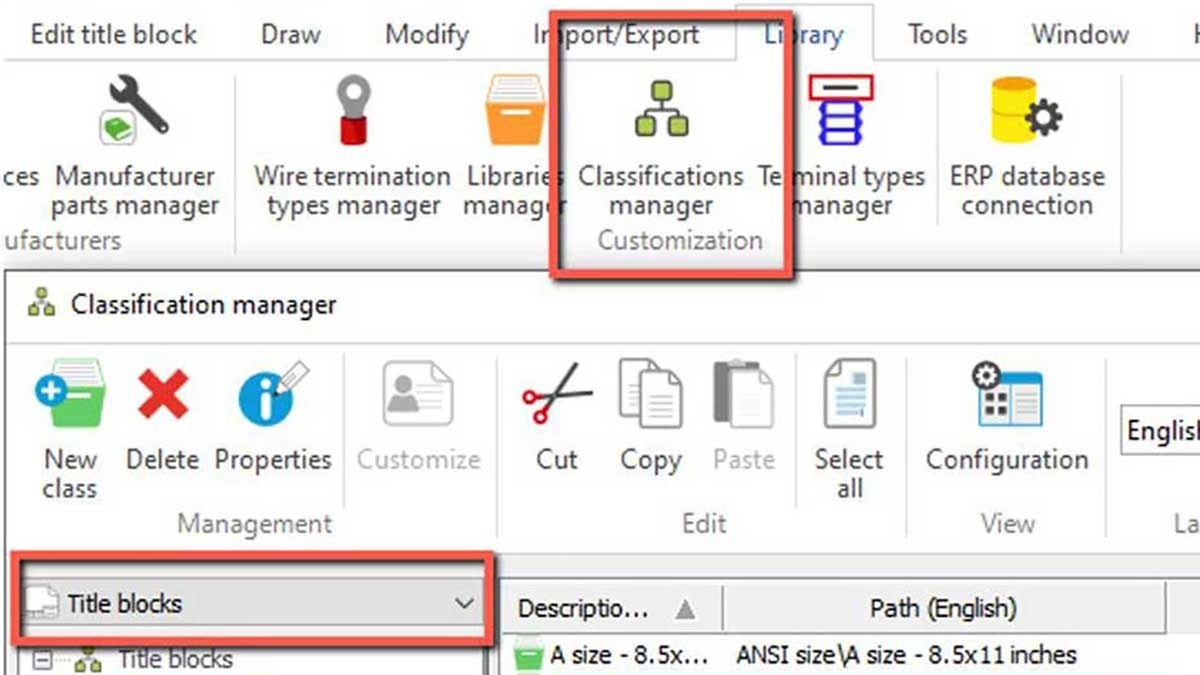
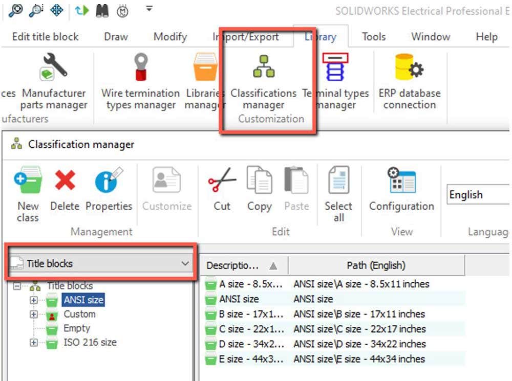
The Classifications Manager (LIBRARY > CLASSIFICATIONS MANAGER) can also be used to create custom title block classes and subclasses. This would be a good way to organize your title blocks in custom categories if needed.
Getting Started
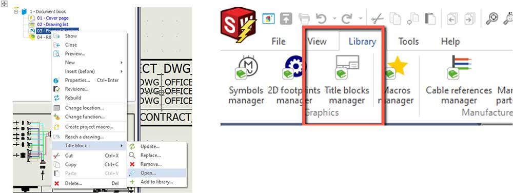
You can modify a title block already associated with a drawing from its contextual menu (RIGHT CLICK DRAWING > TITLE BLOCK > OPEN) or from the Title Block Manager (LIBRARY > TITLE BLOCKS MANAGER)). Unlike a SOLIDWORKS Electrical drawing, a title block is a DWG file that needs to be saved. Don’t forget to do so regularly to avoid losing your work.
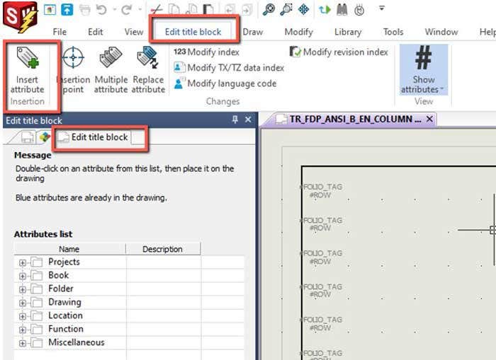
Opening a title block should add an “Edit Title Block” tab in the Command Manager. A similar tab also appears in the Side Panel (next to Documents and Component panel) with a list of attributes that can be inserted.
The PROPERTIES PANEL can be used to set the NAME, DESCRIPTION, and the UNIT SYSTEM of the title block. The unit system should match the units of the project to which the title block will be applied.
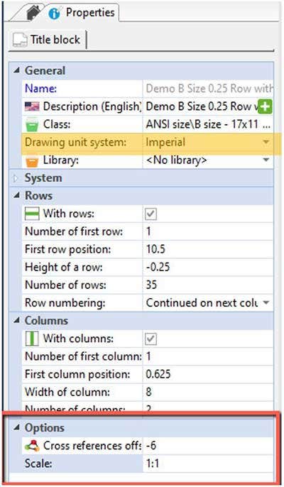
The CROSS REFERENCES OFFSET controls the placement of the automatically inserted cross-reference symbols in a drawing, thereby ensuring uniform positioning. However, the option to use the title block offset for cross references needs to be enabled in the project. The SCALE factor is for 2D cabinet layout drawings only and is automatically applied to all drawing elements.
Status Bar and Drawing Parameters
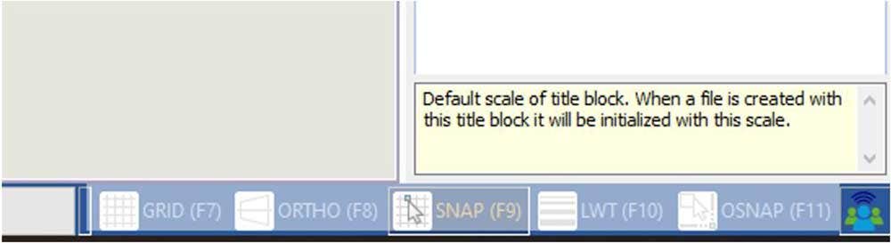
Now that we are going to set up the title block, let’s start with the Status Bar and Drawing Parameters. Having appropriate parameters set up at the title block level can save you a lot of frustration during the drafting process. The Status Bar is located in the lower right corner of the interface and shows the coordinates of the cursor as well as allows you to toggle modes like SNAP, OSNAP, ORTHO, GRID, LWT on and off.
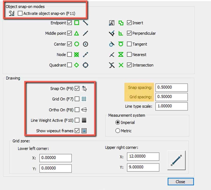
The Drawing Parameters can be accessed by Right-Clicking anywhere on the Status bar. This will allow you to set your GRID and SNAP spacing as well as activate different kinds of OBJECT SNAPS (OSNAP). For those unfamiliar with these options, SNAP causes the cursor to move in increments of the defined spacing while OSNAP will cause the cursor to snap to endpoints, midpoints, centers, etc. of existing entities.
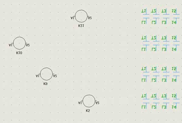
It should be noted that the SNAP and OSNAP settings of a new drawing are taken from the drawing parameters of the title block used. Additionally, most default schematic symbols are set up with a 0.25 in or 5 mm SNAP or a divisible value, which is why a similar SNAP spacing will allow you to work seamlessly with these symbols.
To finish up the discussion on Drawing Parameters, ORTHO will cause the cursor to move orthogonally in X or Y directions which ensures horizontal and vertical drawing or moving of objects. Meanwhile, LINE WEIGHT (LWT) activates the visibility of various line thicknesses. The grid spacing, ideally, would be equal to a multiple of SNAP spacing while the Grid Zone controls the display area of the grid and should vary depending on the sheet size.
Borders and Logo
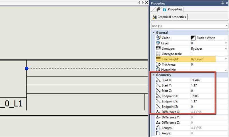
As discussed in the previous section, setting a grid zone equal to the sheet dimensions should help users judge the borders of your title block. DRAW > LINE can be used to draw additional borders, while the blue drag handles on selections can be used to resize existing lines. Use the Properties Panel to set the line weight as well as manipulate X and Y coordinates of the endpoints of the line to align them horizontally or vertically.
A combination of MODIFY > MOVE and OSNAP (Endpoint, Perpendicular, Midpoint, etc.) can be handy in attaching the lines to existing border geometry.
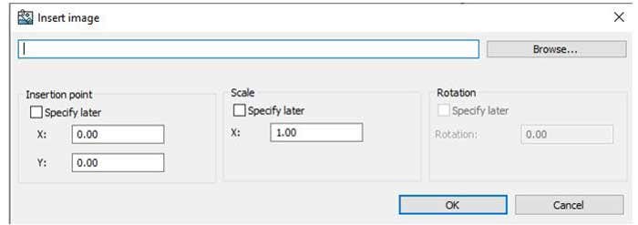
Logos can be inserted by using the DRAW > INSERT IMAGE tool, which only allows for Bitmaps. The positioning, scale, and rotation angle can be set at the time of insertion or adjusted later using drag handles.
This concludes part one of this blog series. The second blog, “SOLIDWORKS Electrical Title Block Tips You Should Know: Part Two” covers adding attributes as well as correctly placing and calculating Row and Column tags in a title block.
If you would like to learn more about SOLIDWORKS Electrical from our experts or if you have any questions, contact us at Hawk Ridge Systems and our team would be happy to support you. Thanks for reading!