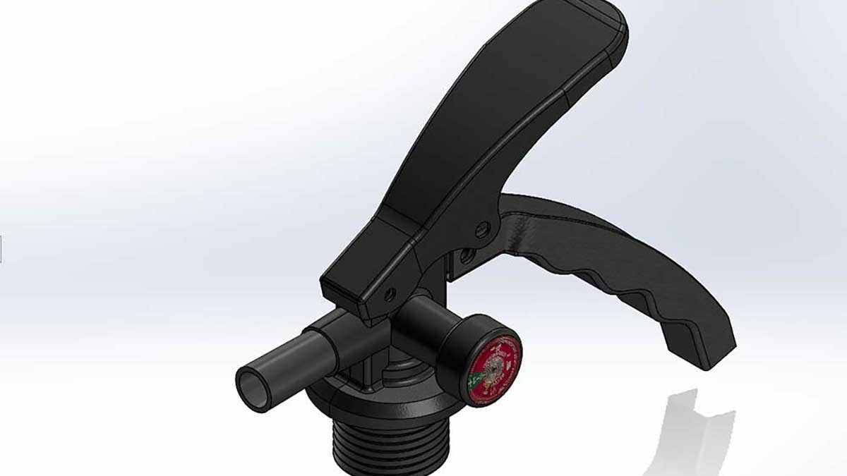
Draft is an important feature in die cast and injection mold manufactured parts. It refers to the taper of faces and walls throughout the part that allow for the demolding process to take place without damaging the part or the mold. SOLIDWORKS provides users with robust and convenient solutions to this design-for-manufacturing problem, and we’ll go through each of them in detail.
Draft Analysis
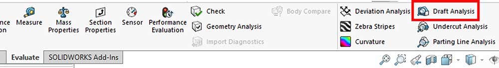
Before applying draft, it’s helpful to know which areas of the design require draft. The “Draft Analysis” tool – found in the “Evaluate” tab of the Command Manager – checks all surfaces of the part for slope in a specified direction of pull for a theoretical mold.
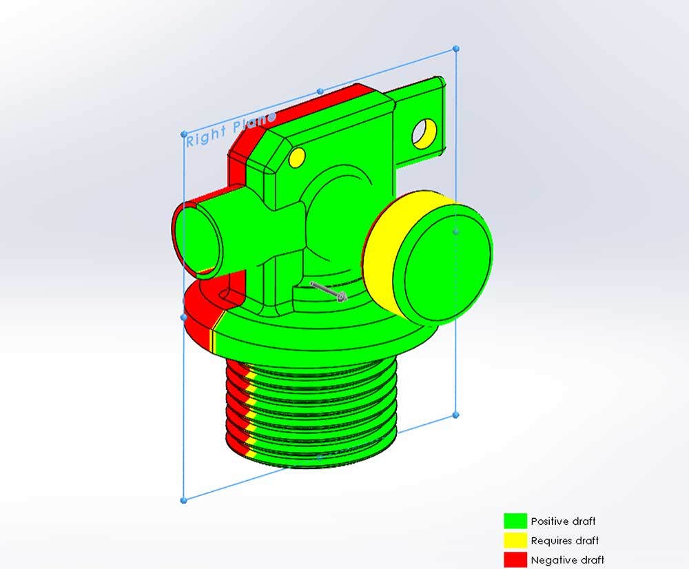
To define draft, SOLIDWORKS needs to know the direction of pull for the theoretical mold. A plane or a planar face must be selected, and then a vector is defined normal to the plane. SOLIDWORKS looks at the part’s surface in all directions and evaluates the degree of slope toward that vector. Anything parallel with the direction of pull is considered to have zero degrees of draft. A minimum amount of slope can be specified as the required draft, and any angle that meets or exceeds this is considered positive draft (green). Next, any angle of the surface that is sloped toward the direction of pull but does not meet the necessary amount of draft is considered as requiring draft (yellow), and anything sloped away from the direction of pull is considered negative draft (red).
Draft Toggle
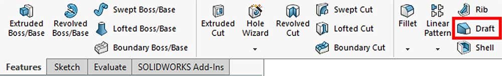
The Boss-Extrude, Cut-Extrude, and Rib features all contain a “Draft Toggle” in their property manager. This toggle allows the degree of slope to be input and tapers the profile along the extruded path accordingly.
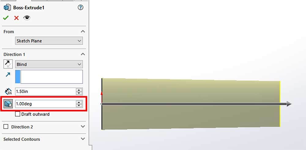
It can be toggled on and off to switch between a nominal design and production design, as well as switch between a material positive or negative condition. For a bi-directional extrusion, draft can be specified separately for each direction. The inner and outer surfaces of an extrusion can be drafted in the same feature but will be applied in opposite directions.
Draft Feature Options
While the Draft Toggle is useful, in many cases it is not enough to fully draft the surface of a part. This is because it is limited to the direction of extrusion. To apply draft in any direction, the amazing “Draft” feature can be used to define it in one of three different ways: neutral plane, parting line, or step.
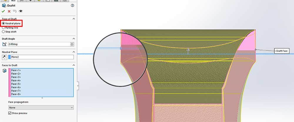
Neutral Plane
The “Neutral Plane” option works similarly to the Draft Analysis tool in that a plane or planar face must be selected that defines a normal vector for the direction of pull. The plane is considered “neutral” because geometry intersecting this plane stays constant, and the part’s surfaces pivot about this plane. Note that this applies even if the surface does not physically cross the plane; it will pivot about its theoretical intersection with the plane toward the direction of pull.
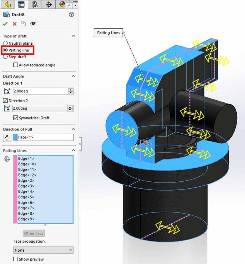
Parting Line
The “Parting Line” option pivots surfaces about a specified edge, typically a split line. (The Split Line command is used to project geometry onto an existing face to define a new edge, effectively splitting it into two or more faces.) This is similar to Neutral Plane draft, but it treats the parting line as the neutral plane; in other words, the surface pivots about the line. Depending on the part requirements, the parting line can include arcs and other geometry; for this, Parting Line draft can offer a significant advantage over Neutral Plane draft. Cylindrical faces cannot be drafted this way. The direction of pull is specified as before by selecting a plane or planar face. One or both sides of the parting edge can be selected, each with their own degree of draft.
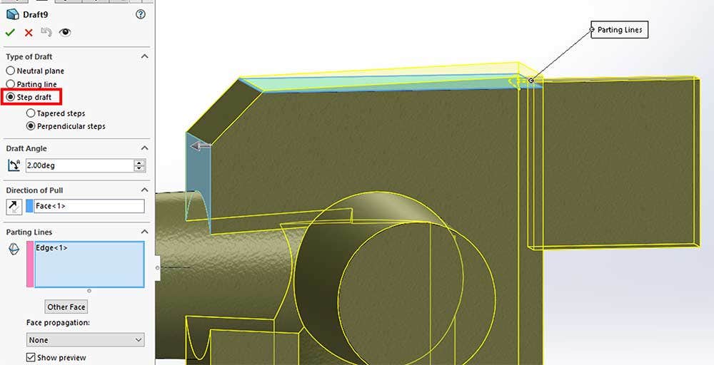
Step Draft
The last type of draft available in the draft feature is Step Draft. When the draft is added, a step is created at a specified parting line. Again, a Split Line feature was used to create this edge. A direction of pull must be specified, but take care in doing so because the final result changes based on this selection. This surface acts as the neutral plane – the surface pivots about its theoretical intersection with this plane, and a step is created at the parting line to compensate. With the tapered steps option, the newly raised surface can be tapered at the same degree of draft.
For more information on SOLIDWORKS or if you have any questions, contact us at Hawk Ridge Systems. Thanks for reading!


