How many of you have been using configurations? Show of hands? Well, did you know that you can set up multiple configurations and modify several parameters at once with a Design Table? If not, this is your lucky day because this article is a look at Design Tables in SOLIDWORKS.
 |
1. Start with Configurations
Assuming that you’re already familiar with configurations, I won’t go too in-depth on them, but these give the user the ability to change geometry, creating multiple part iterations within one part file.
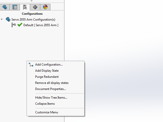
If you’re not using a Design Table, your current process could look like this: click on the Configuration manager, right-clicking in the blank area and clicking on Add Configuration.
|
|
With a Design Table, you can create multiple configurations at once while adding in all the parameters you’d like to change, all inside the Excel interface.
2. Quick Housekeeping Before Creating Design Tables
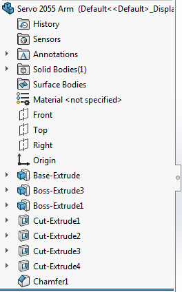
Before I create a Design Table, it’s a good practice to do some model housekeeping. The first thing I want to do is rename the features in the Feature Manager tree from the default names. I’m going to do this by clicking on the feature and hitting F2 on my keyboard. I’m changing Cut-Extrude3 to Shaft Hole and will focus the Design Table on this feature.
|
|
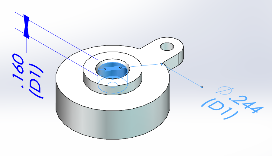
3. Expose Dimensions
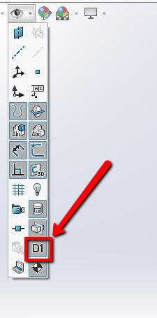
Once that is done, I want to expose the dimensions. I can do this a couple of different ways, such as right click on the Annotations folder and hit Display Annotations, but I will double-click on the Shaft Hole since that’s all I’m modifying. There is something else that I’d like to turn on, and that’s in the Global Hide Show menu in the Heads Up Toolbar. I want to turn on View Dimension Names.
|
|
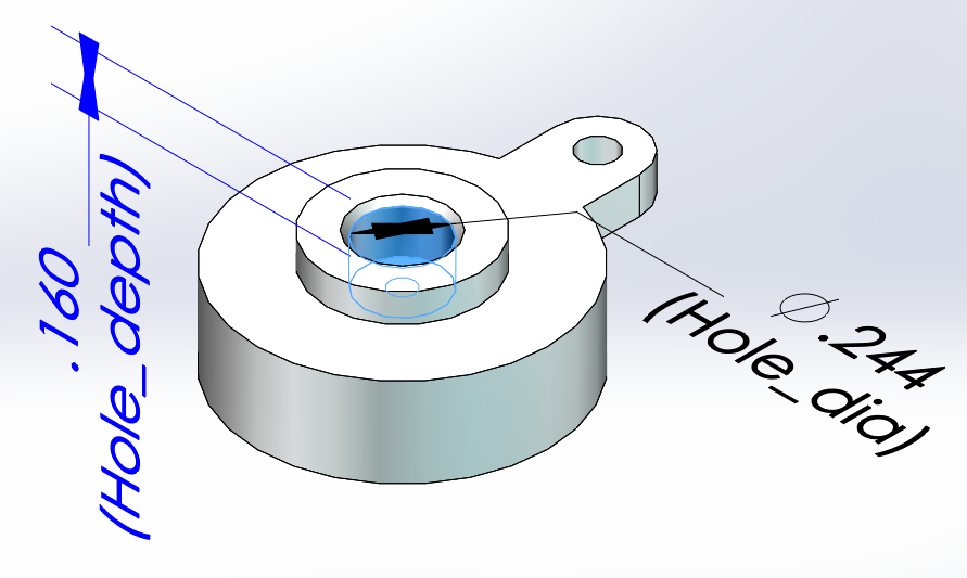
4. Give Your Dimensions Specific Names
Now, when I double-click the feature, I can see the dimension values and their names. Again, these are generic, so I’ll double-click each dimension to give them a more specific name in the Modify box. One will be Hole_dia and the other one will be Hole_depth.
|
|
|
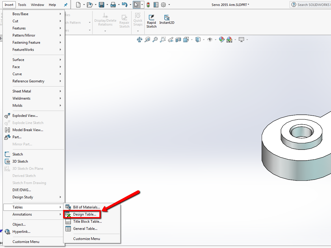
5. Create Your Design Table
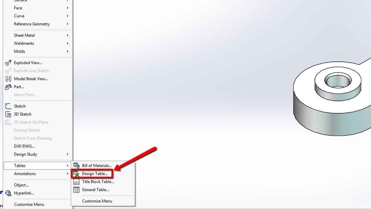
That’s enough set up for now, but you’ll see why all the setup steps were important shortly. Creating a Design Table is easy, just click on Insert, go to Tables at the bottom and select Design Table.
|
|
The PropertyManager gives us a few choices. I’m going to select the first one, which will create a Blank table. If you select Auto-create, it will look at the part and pull in all existing configurations and the differences in those configurations, which is helpful if you’re working with a part that you’ve already created multiple configurations for.
The last choice is From file, and this would read in an Excel file. I wouldn’t recommend doing this for starting a brand-new table, but if you have an existing table saved out for another part, you can use this option to import that table. The key is that you will need to relink the parameters.
|
|
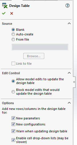
Edit control lets you either change the model and has it update the Design Table, or force you to make all changes through the Design Table. The options down at the bottom will add parameters and configurations to the Design Table if they are added to the model.
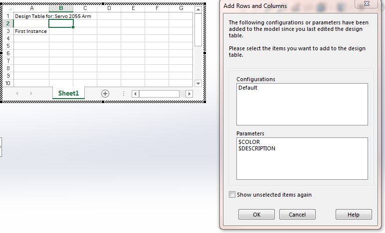
Once we hit the green check, the first thing you notice is the table that looks like Excel that opens up. Also, a dialog box pops up asking if I’d like to add any existing configurations or parameters to the table. I’ll select the Default configuration and hit okay.
|
|
6. Determine Items to Suppress or Unsuppress
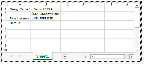
Now that you have created the table with the settings from Step 5, anything you double-click on will be added to the Design Table. If I double-click on the Shaft Hole, it will be added with the ability to suppress or unsuppress it.
Another thing to note is that the Design Table has a very specific format. Cell A1 has the title of the table, and A2 is blank. The A column is where configuration names are put and Row 2 is where the parameter names are put. The values are filled in the grid beneath.
|
|
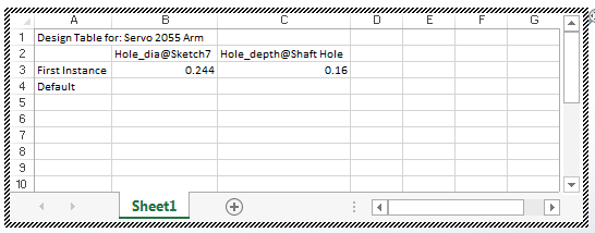
I’m going to delete the B column because I don’t want to suppress or unsupress the feature, and then I’ll click in the B2 cell and add in Hole_dia and then Hole_depth in C3. Now, you can see why naming those dimensions is important. When I look at the Design Table, I can tell which dimension refers to which.
|
|
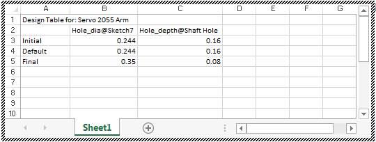
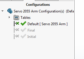
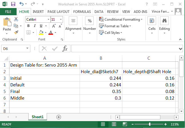
I’ll change that default First Instance name to Initial and add in a Final configuration under Default. I’ll copy the initial values to the Default configuration, and create .35 and .08 for the values for Final.
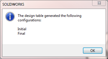
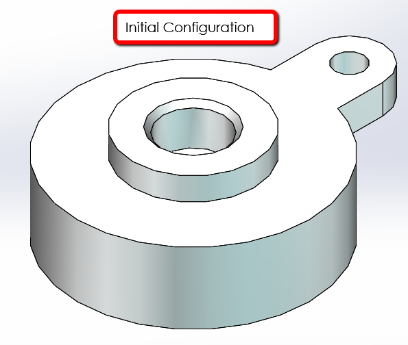
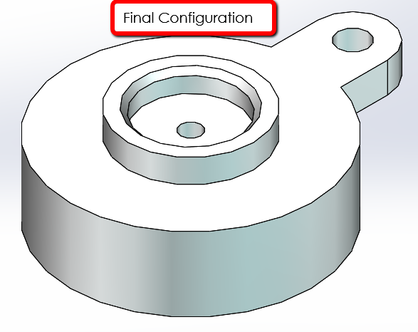
If you click off in the Graphics Area, it takes you out of the Design Table and it says that those two new configurations were added. I can double-click through the configurations I created and see that the design has changed.
|
|
 |
 |
 |
 |
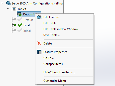
7. Editing Your Table in Excel
To get back into the Design Table, expand the Tables folder and right-click on the table. Editing the feature will take you back into those options when you first set up the Design Table. Edit table brings the table back into the graphics area, but a nice feature is the ability Edit Table in New Window. This opens it up in Excel. I’ll add in another Configuration, Middle and add dimensions of .3 and .12.
 |
 |
We can also right-click on the table and select Save Table to save it externally. You can use it for another part and be able to update it in Excel directly without opening SOLIDWORKS. Keep in mind, you will need to link the external file to the part and link the parameters as well.
That’s it for this blog on creating a Design Table. I hope that you find them as useful as I have. If you have any questions about Design Tables, contact us atHawk Ridge Systems. Thanks for reading!


