Many people have been using configurations on the SOLIDWORKS side but are not aware of the possibility of using CAM configurations in SOLIDWORKS CAM Professional. Different CAM configurations can be created to program different versions of the same part or those with geometric changes.
We will review how to create a mill configuration and a turning configuration, and use the exact same part that was used in the previous configuration to be worked on.
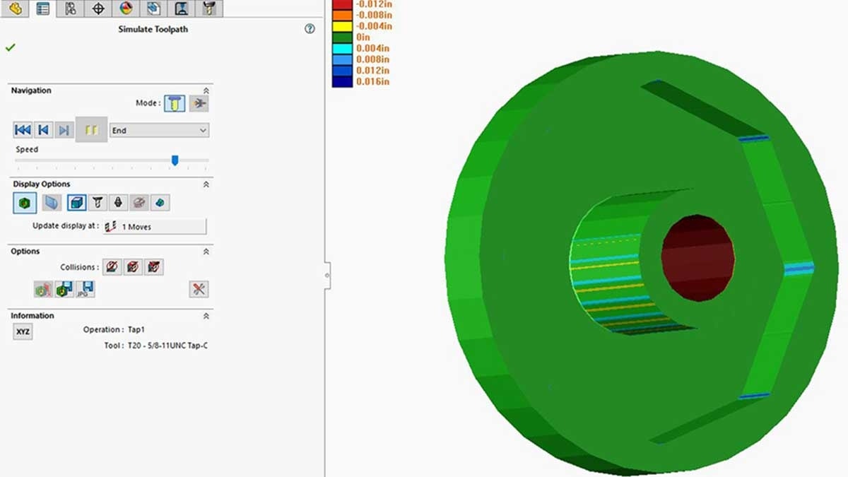
Start by putting the part in a turning environment, which can be done in SOLIDWORKS CAM Pro. The process remains the same as far as setup is concerned – we set up the machine, Stock Manager, and the Coordinate System. We are then going to click Extract Machinable to have features created. Afterward, we can generate the Operation Plan and Tool Path. When we simulate the tool path and get the result, there is a way to save the part after it has been worked on.
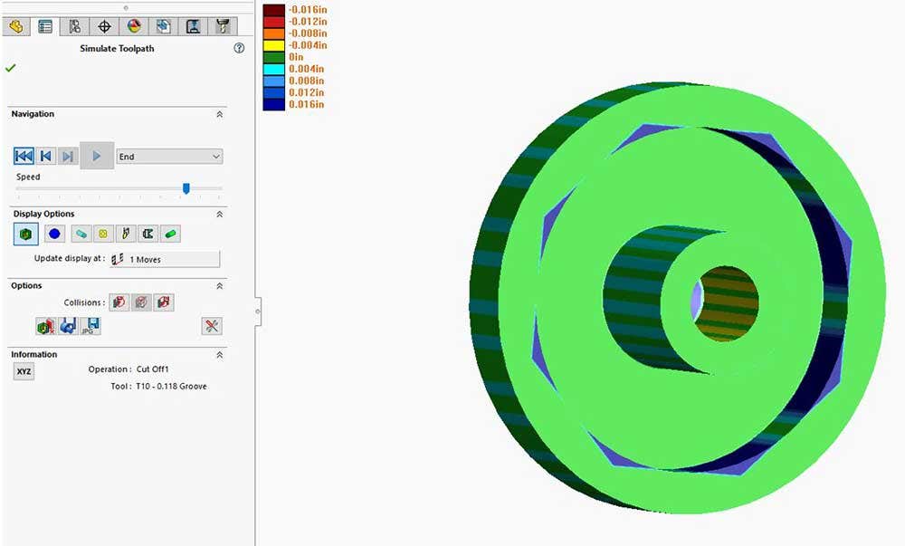
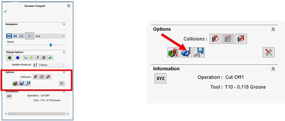
To do that, we click at the bottom where the Save WIP as STL button is at. We can save the part with the name Turn Config.
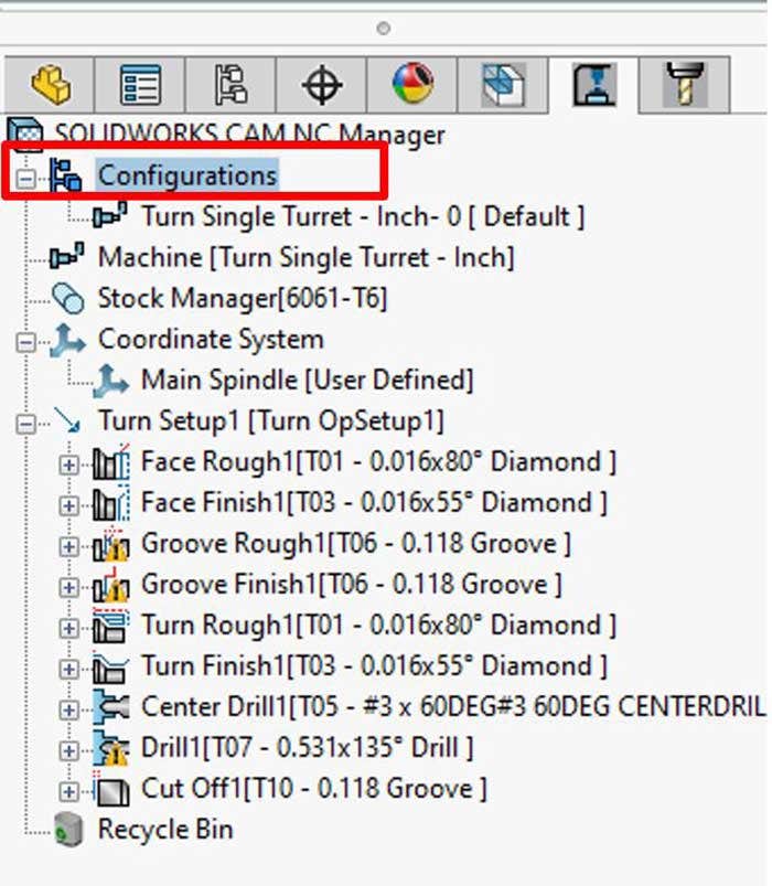
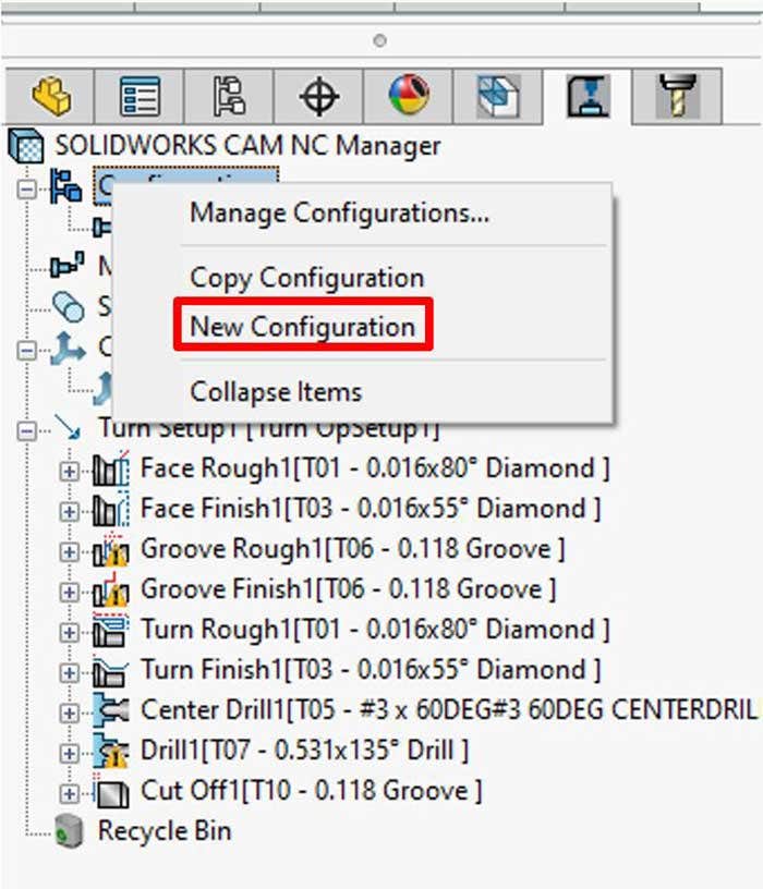
Now our next move will be to create our Mill Configuration. Right click where it says Configuration on the CAM Feature Tree. There in the right click menu, we can now click on New Configuration. We will name It Mill.
Of course, once again we will setup the machine, Stock Manager and Coordinate System. The biggest change that we will be doing is incorporating the STL file that we had previously created in the turning configuration. To do that, double click on the Stock Manager in the CAM Feature Tree. To get the STL file to be recognized, we now click on the STL Tab. Once the tab is activated, we can now grab the STL file Turn Config.
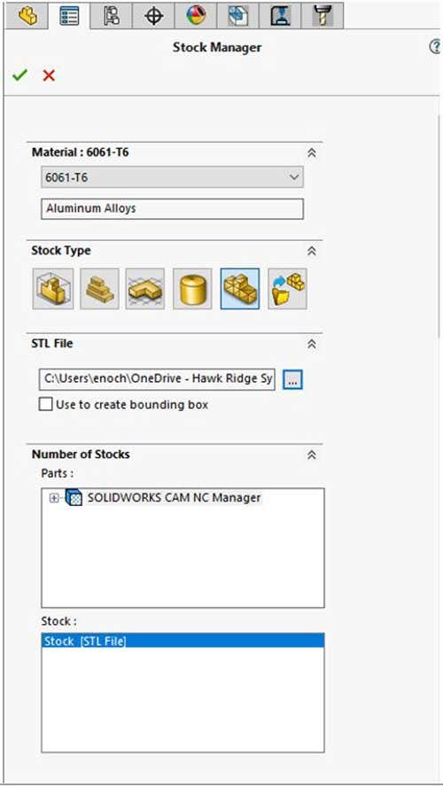
We will notice that the part Turn Config still has some material on it, as expected. After setting up the Coordinate System, we will Extract Machinable Features. Then click on Operation Plan and Tool Path. Now we will run the simulation and see that the part starts off with the amount of material that was left over after being on the turning operation.
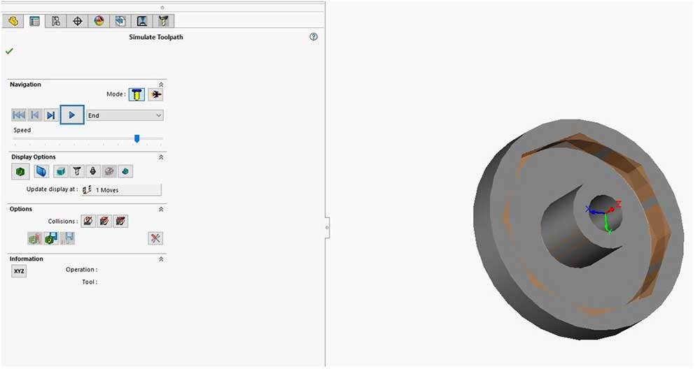
The milling begins and the remaining material has been milled off.
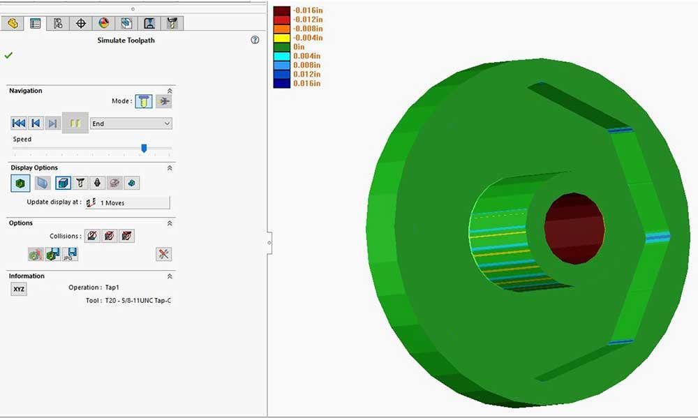
Finally, our part has been completed. We saw how easy it is to incorporate configurations on the CAM side. It wasn’t enough to create a different configuration, but to use two separate operations with the same part to get our result. For more information on SOLIDWORKS CAM or if you have any questions, contact us at Hawk Ridge Systems today. Thanks for reading!


