Composer Quick Tip - Measurements

Composer Quick Tip – Measurements

Table of Contents


Dimensions

Let’s face it, not everyone is a wizard when it comes to looking at standard
views shown on a drawing, picturing the part or assembly and on top of that
understanding the accompanying dimensions. I often take for granted the
training I received in school. To this day there are occasions where I need
to stare at the drawing for I bit before I can picture what’s going on.
Measurement - Author Tab

That struggle takes time, adds frustration and can often lead to mistakes.
With the help of
SOLIDWORKS Composer
we can get those dimensions off of your engineering drawing and into a format
that allows just about anybody to understand the information you’re trying to
get across.

Measurements… Where Are They?

SOLIDWORKS Composer’s annotative Measurements are all neatly organized in the
Author tab. Being in the Author tab should immediately tell you that we are adding
collaborative actors and they will be organized in the collaborative actors
section of the Left Pane after we add them. You’ll notice that almost all of
them have drop-downs so using them effectively comes down to finding the right
tool for the job.

Before you use them make sure your unit system is set up correctly. This can
be checked in the document properties the input should reflect the unit system
the part was designed in. For SOLIDWORKS Files this should always be set to
millimeters. The output should reflect the unit system you want to see in your
measurement annotations.

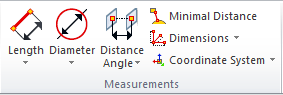
Length and Diameter Toolset

The first set of tools are the Length and Diameter commands. They can be used
to add measurements for the length of edges, both circular and linear. Their
primary job in Composer is to allow you to show dimensions of single part. The
properties for the Measurements are similar to a label so remember to set up a
Style to get that a consistent look. They also have a section for GD&T
annotations so they can act as an informal substitute for the inspection
drawing.

A few quick tips on the tools:

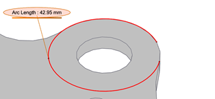
To flip the direction of a circular edge measurement look for the
“Complementary” Property and select “Proceed”, not exactly the most obvious
property change.

Measurements: flip direction of circular edge


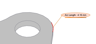
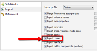
The curve length tool requires an actual curve and cannot be applied to an
edge. If you would like to use this tool for pipe lengths or any other
curvy shape remember to check the box to Import curves. This does not work
for SOLIDWORKS curves unfortunately, same with the Import points.

Measurements: import curve


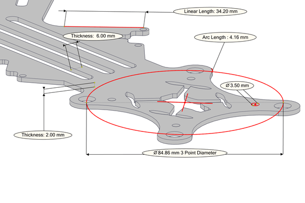
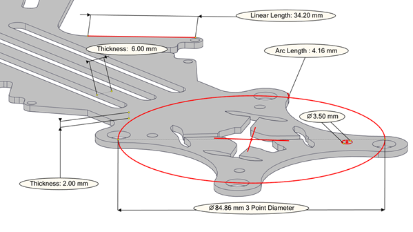
The thickness Measurement is probably the most interesting in this toolset. It
creates a thickness measurement by drawing a line normal to whatever surface
you select. Because of this straightforwardness I’ve found it to be one of my
go-to tools. I don’t need to worry about finding an edge or a vertex and the
callout becomes very clear in a 3D format.

Next to the length tool is the diameter measurement. It can create radius or
diameter callouts. The input needs to be a circular edge, unless you are using
the 3 point version in which case the input can be any three points on the
model. If you want to place a circular dimension to show a circular pattern of
holes hold the “alt” key while placing the dimension and hover of the
cylindrical faces of the holes. This will detect the circular edges and pick
up on the center point.

Measurement

Next to the length and diameter commands is a long list of other tools to
create measurements. The idea behind breaking them off into their own list is
that these tools are more useful to create dimensions between two or more
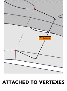
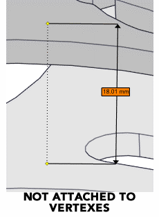
components. All of these tools are associative so as you move actors around
the annotations will update with the new position. In order to have that
associativity with your actor position keep an eye on the tool tip when
placing the annotation. If it shows up as red that means you are about to
attach it to the correct corresponding geometry. Yellow means it’ll be
attached to a geometry actor but not at any specific location.

Measurements: attached to vertexes
measurements: not attached to vertexes


The Chain and Fan dimensions are a way to continuously add dimensions either
as a chain, so one click establishes the first reference and from there the
annotations will continue to “chain” from point to point or fan out from the
original point.

In the end, dimensions are about as straight forward as they can be. With a
host of options in the Composer toolset you can easily find the right tool for
the job.

Want to learn more about how SOLIDWORKS Composer can improve your product
communication and help you leverage existing 3D CAD data? Watch the video:
Results in 90 Seconds With SOLIDWORKS Composer

Hawk Ridge Systems Resource Hub

Hawk Ridge Systems Resource Hub

It often takes a team to solve a problem – and sometimes it takes a team to write about it. The Hawk Ridge Systems Engineering Team is comprised of our Product Managers, Applications Engineers, and Support Engineers. They've collaborated on this article to bring you the most accurate information about the solutions you use for design and manufacturing.
0 0 votes
Article Rating
Subscribe
Notify of
guest

4 Comments
Oldest
Newest Most Voted
Inline Feedbacks
View all comments
Sue Partin
Sue Partin
2 years ago

Hi — As a Composer newbie I have learned quite a bit from your web tutorials and tips (thanks!). However, I’m struggling with accurately measuring vertical distances in an orthographic view of a model. For example, while looking at the left side of the model, I’m trying to measure the “Z” distance between the bottom of a caster wheel and the centerline of an electrical connection on the side. The measurement tools in Composer don’t seem to provide this option; instead, using “plane to point” usually gives me an angular measurement. “Point to Point” produces a true (“as the crow flies”) distance. Is there a way to control these tools so I can get true X, Y, or Z measurements between two actors? Any advice or suggestions you can provide will be appreciated.

Scott Woods
Scott Woods
2 years ago

Hi Sue,
Thank you for the detailed description of what you’re trying to achieve. I think I have a solution that is going to work for you but first a little background on 3D measurements. When you bring a SOLIDWORKS assembly into a drawing it essentially flattens it to 2D, which makes measurements simple. In Composer the model is always in 3D so the measurement attachments are located in 3D space. This goes the same for PMI dimensions using DimXpert (MBD Dimensions).
With that said any point to point measurement is going to take the shortest path between those two points and if the selected points are not completely vertical or horizontal to each other the measurement will be at an angle.
For this case, I think a plane to plane measurement will work the best since the dimension will be perpendicular to the plane on both ends of the measurement. It sounds like one reference surface is already in place and we just need to add one to the center point on the end of the wire/connection. You have two options here. The first option would be to use a primitive surface (plane) in Composer, attach it where you need to measure to and use the plane to plane measurement. After placing the measurement you can set the opacity of the primitive all the way down so that it is invisible.
The alternative method would be the same, except you would be making the reference plane in SOLIDWORKS CAD as a flat surface attached to the point where you need to measure. You would then set the opacity of the surface in Composer all the way down so that it is invisible.
A third method that just came to mind would be to cut or extrude some sort of flat reference body in SOLIDWORKS CAD at any measurement location so that in Composer you can use the plane to plane measurement tool without any additional surfaces or primitives needed. These features can be very small and just used for reference in Composer.
I hope that helps.

Joseph Sarhadian
Joseph Sarhadian
2 years ago

Hello,

Is it Possible to overwrite a distance dimension value?
Also, How Can I change the unit from MMGS to IPS?

Thank you,
Joseph

Scott Woods
Scott Woods
2 years ago

Hi Joseph,
In Composer you can switch the input and output UOM from “File > Properties > Document Properties > Units”. Keep in mind this is a direct conversion, you will need to match up the input with the what the CAD input is, then switch the output to the corresponding value. Also, you can override any dimension value. You will need to drop down the properties menu for “Measurement/GD&T” and uncheck the box for “Display Value”. This will clear out the measurement, then you can type anything you like in the “Middle String” section. Anything typed in this field will display as the dimensional value.
Let me know how that works out for you.
Scott Woods