If you’ve been struggling with Loft or Boundary features in SOLIDWORKS, fear no more! Known for being two of the more complex features in the program, Loft and Boundary features often require precise selections and careful sketch management for the most accurate and attractive results. In this article, we’ll show you three simple tricks to take your Loft and Boundary Features to the next level while avoiding errors and bad geometry.
Select Profiles in Consistent Locations
With simpler features such as Extrudes and Sweeps, you may have been able to get away with selecting sketches in the FeatureManager or graphics area without giving much thought to where (specifically) you clicked on the sketch when selecting. With Loft and Boundary features, we must be much more precise in how we select sketch profiles, even in relatively simple scenarios.
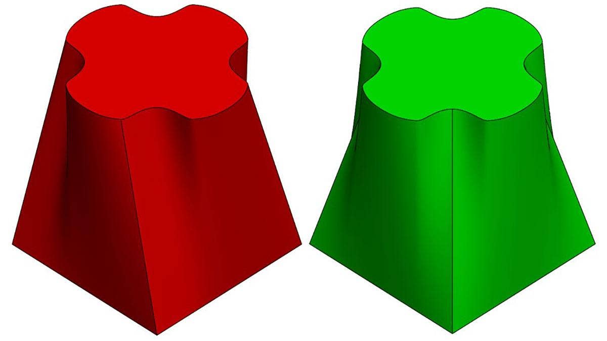
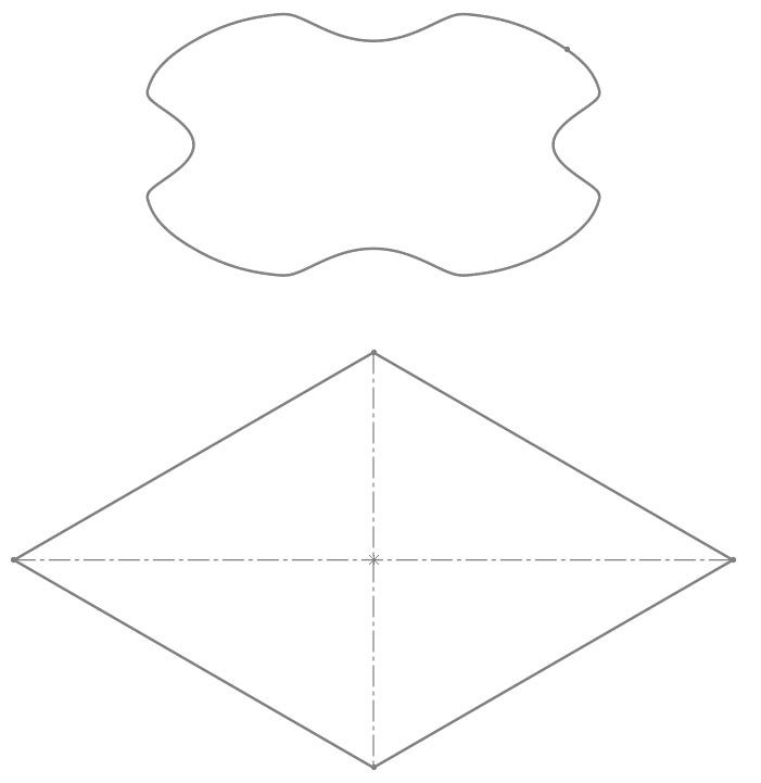
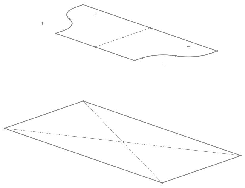
For example, the models below were created using the same two sketches – on the left, the sketches were selected from the FeatureManager Design Tree (similar results would be seen if the sketches were chosen graphically at inconsistent locations). On the right, consistent and corresponding points (one in each sketch profile) were selected:
Inconsistent Profile Selections (Left), Consistent Profile Selections (Right)
More specifically, the following endpoints were selected on each profile to create the models shown above:
Geometry Differences Resulting from Profile Selection Points
Clearly, the green model on the right of Figure 1 is the desired geometry, and the only difference between these two models is how the sketch profiles were selected. If you have difficulty deciding where to select your profiles, imagine tracing lines between the profiles to create wireframe geometry. Where would the lines start and end? For best performance, also make sure that you select points on the profiles (junctions between sketch entities) and not entire lines, arcs, etc.
Ensure Profiles Have the Same Number of Sketch Entities
This step often overlooked even by experienced SOLIDWORKS users, and can be the difference between a perfect Loft/Boundary and one that fails completely. When Loft profiles are selected properly, connectors are added between matching points in each profile, usually at the junction between each pair of sketch entities. So long as the total number of sketch entities (lines, arcs, splines, etc.) in each profile is the same, this process is typically automatic. In the figure below, the lower profile is a simple rectangle consisting of four line segments, while the upper profile consists of two lines, one arc, and one spline, for a total of four sketch entities. Since each profile contains four sketch entities, four connectors are automatically mapped to corresponding points upon selection, and our work is done!
Loft Preview between Profiles with the Same Number of Sketch Entities
When this is not the case, however, bad geometry is nearly unavoidable, and we must make some modifications to the profiles to make the number of sketch entities consistent. To do this, we have three tools at your disposal: Split Entities, Segment, and Fit Spline.
Split Entities
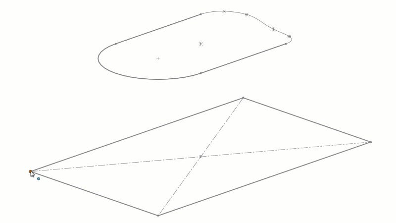
Suppose one of your Loft profiles is a single continuous spline, and you intend to Loft it to a square. The spline consists of only one sketch entity, while the square has four:
Loft Profiles with Inconsistent Number of Sketch Entities
While you could certainly achieve some sort of successful Loft feature using these sketch profiles as they are, the resulting geometry is likely to be irregular due to the inconsistent number of sketch entities in the profiles. The Split Entities command can assist us in solving this issue by breaking individual sketch entities into multiple pieces. Split Entities is not available in the CommandManager by default and can only be used while editing a sketch. To use Split Entities, first edit a sketch, then navigate to Tools > Sketch Tools > Split Entities. Once active, simply click a sketch entity in the position where you would like to split it, then confirm the command. Split points maybe be moved freely or constrained using sketch relations, dimensions and/or construction geometry as required.
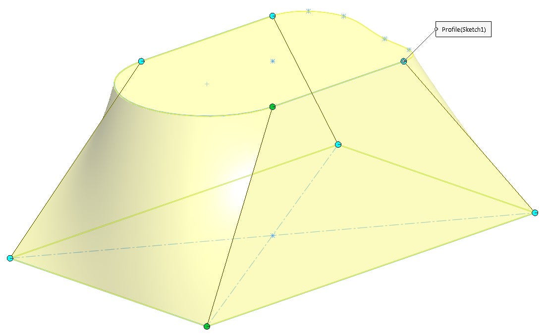
In this case, the continuous spline profile was split four times, breaking it into four equal segments and rendering it consistent with the square profile. Construction geometry was leveraged for the positioning of the split points:
Splitting a Continuous Spline into four Segments using Split Entities
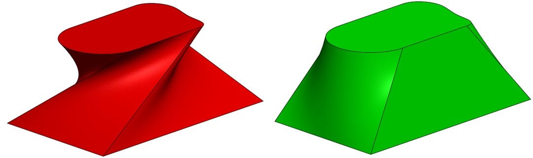
The end result is a symmetric model with predictable geometry, as seen in the figure below in green. The red model on the left is the original geometry, resulting from using the profiles without first using Split Entities:

Results with Inconsistent (Left) and Consistent (Right) Number of Sketch Entities
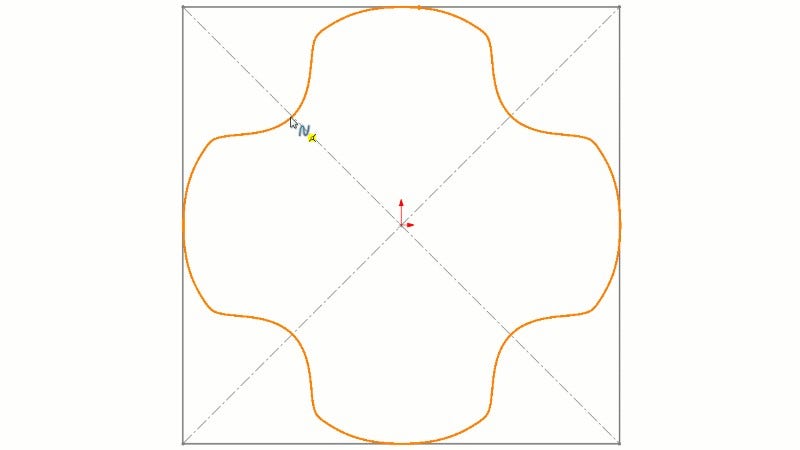
Segment
The Segment command is similar to Split Entities in that it too can be used to break sketch entities into multiple pieces, with one additional detail – it breaks them into equal segments. This tool is particularly useful and efficient when you don’t need the flexibility of manually positioning the split points. Like Split Entities, Segment is not available in the CommandManager by default. While editing a sketch, navigate to Tools > Sketch Tools > Segment to activate the command. In the example shown below, a single ellipse is being broken into four equal segments. When using this command in the context of Loft/Boundary features, ensure that the Sketch Segments options is enabled – the Sketch Points option does not split the sketch, instead only adding reference points. Then, simply click on the entity you’d like to segment and confirm the command.
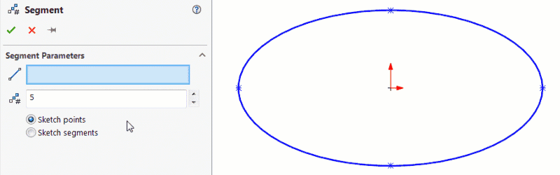
Using the Segment Command
Sometimes, it may be necessary to use Split Entities or Segment commands even when the number of sketch entities in your profiles are the same. This is often the case when connection points in your profiles don’t match up the way you’d like. In this example, two square profiles are used, but are rotated 45 degrees with respect to one another. A Loft feature with no sketch modifications induces twist into the model; using Split Entities or Segment to produce eight connection points in each profile eliminates this twist, as seen below:
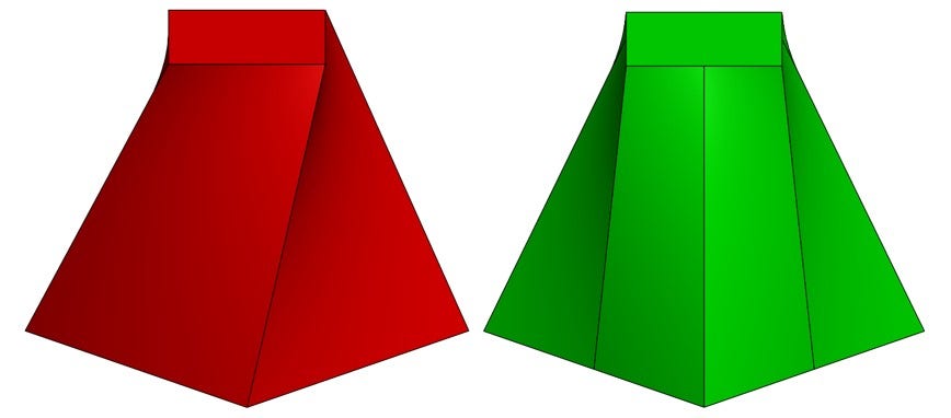
Using Split Entities on Profiles with Equal Number of Sketch Entities
Fit Spline
Split Entities and Segment are great for breaking up sketch entities, but what if you want to combine sketch entities? That’s where the Fit Spline command comes in. Just like the name suggests, Fit Spline literally fits a spline onto your original sketch geometry, combining any included sketch entities into one single piece. While this tool can be extremely useful for Loft/Boundary features, it must be noted that the resulting geometry will be an approximation of the original geometry, and as such, it should be used with discretion.
In this scenario, our lower profile is once again a rectangle with four total sketch entities. The upper profile, however, consists of two horizontal lines, four vertical lines, and two pairs of tangent arcs for a total of ten sketch entities:
Loft Profiles with Inconsistent Number of Sketch Entities
While it may be possible to break up the rectangular profile using Split Entities, the resulting geometry will likely be undesirable, and the split points will be difficult to position. Instead, we can use Fit Spline to convert the chains of vertical lines and tangent arcs in the upper profile into two continuous splines, resulting in four total sketch entities.
Again, Fit Spline is not available in the CommandManager by default, so to use it, edit a sketch, then navigate to Tools > Spline Tools > Fit Spline. Once active, select the sketch entities you’d like to join together. If the entities are intended to form a closed contour, enable the Closed Spline option – in this case, we’ve left it disabled. Typically, Delete Geometry is also left unchecked, leaving the original sketch entities intact as construction geometry.
Then, decide whether the resulting spline should be constrained to the original geometry (can still be modified via dimensions, etc.), unconstrained (free to be modified) or fixed (completely immovable). Finally, set the Tolerance field to an acceptable value. Lower tolerance values will result in closer approximations to the original geometry, but may lack smoothness:
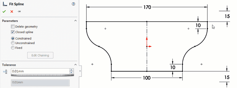
Fit Spline PropertyManager and Results
Once completed for both sides of the sketch, the profiles can be used as in the previous examples. Below, the red model illustrates a Loft using the original sketches, while the green version shows the same Loft with the upper profile modified using Fit Spline:
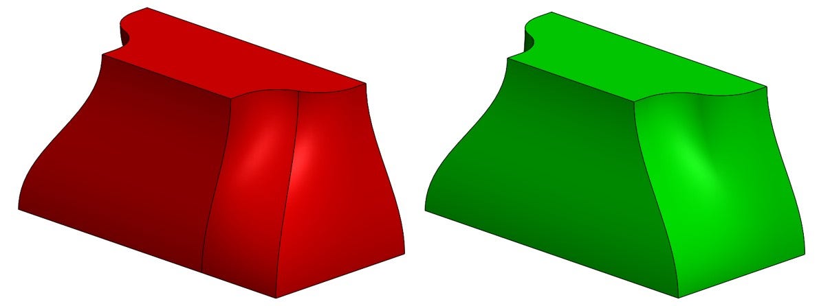
Results Before (Left) and After (Right) Using Fit Spline
Using the three techniques outlined above as required in addition to selecting Loft/Boundary profiles at consistent locations should get you off to a great start, and will likely result in more predictable and consistent geometry.
Manually Adjust Connectors as Needed
Every once in a while, you just want to “fudge it,” right? If you’re not concerned with precisely placed connectors or perfectly accurate geometry, you may be able to achieve an acceptable result by manually modifying the connectors between profiles.
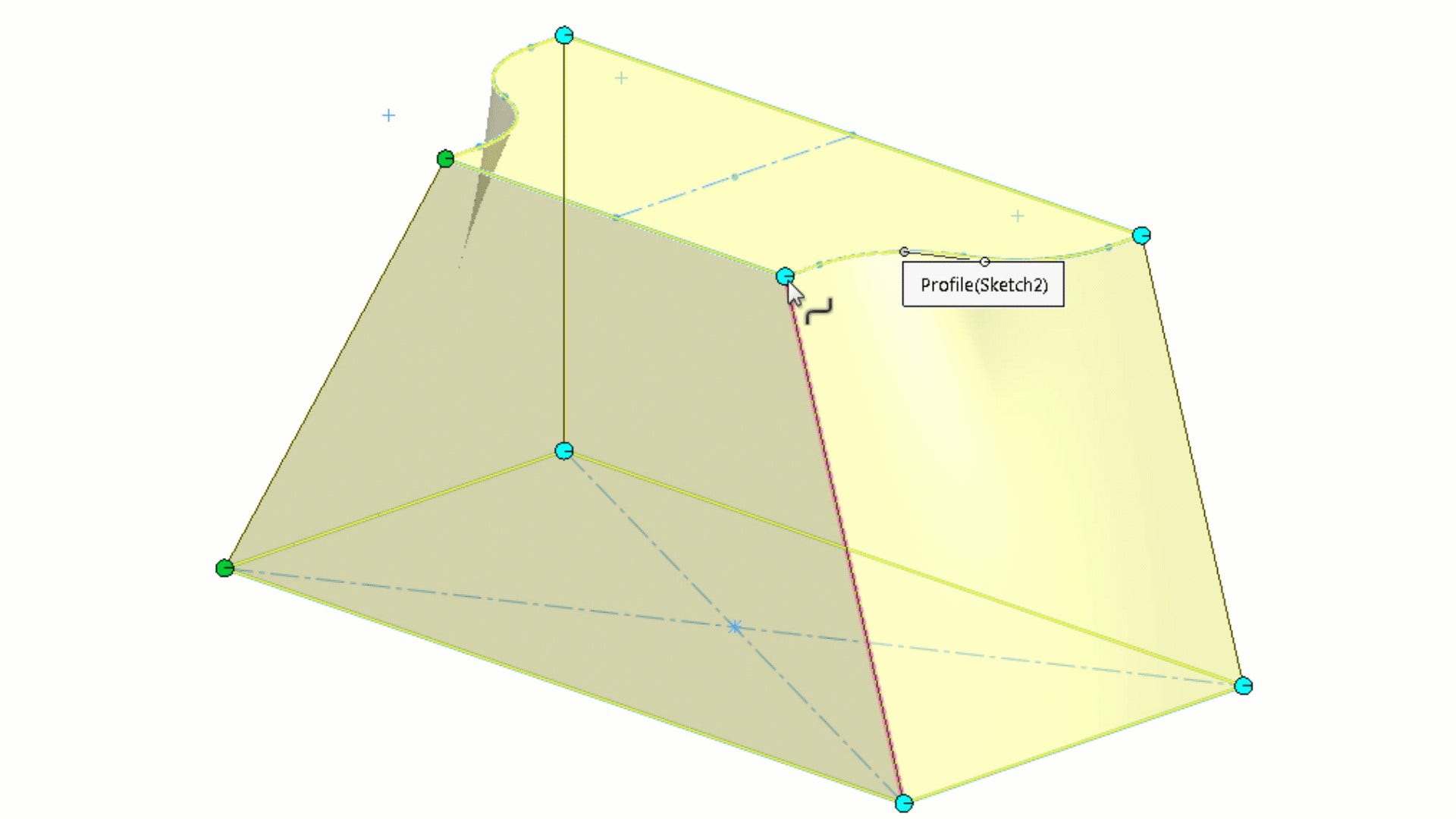
While creating (or editing) a Loft/Boundary, you’ll likely see a single connector on the preview – but remember, the system actually creates a connector for each matching set of points in the profiles. To see all of these connectors, right-click one of the green handles on the existing connector, then click Show All Connectors. The previously-hidden connectors should now show on the screen.
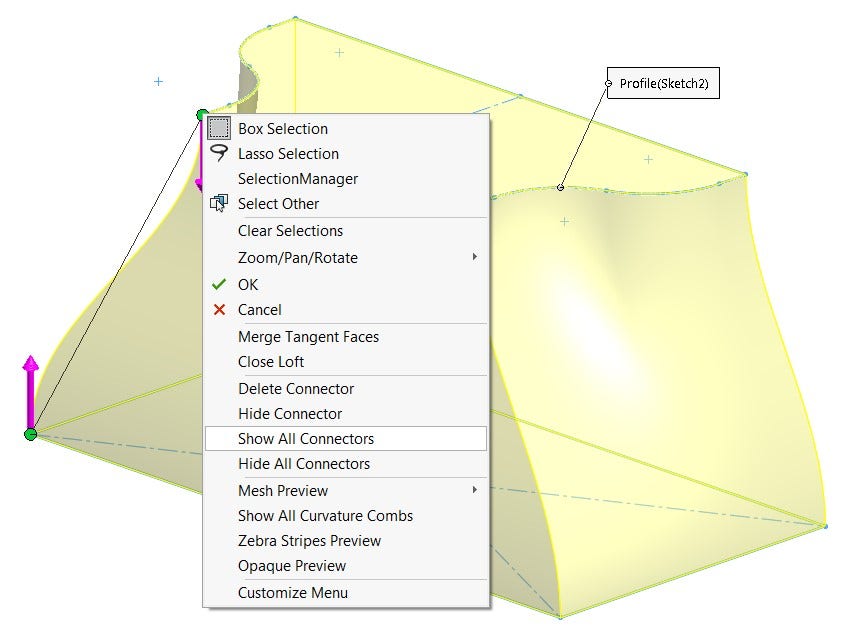
Showing All Loft Connectors
Now, simply left-click and drag a connector endpoint to modify it. Changing the position of connection points will remap the geometry accordingly, allowing you to fine-tune the shape to your liking. Additional connectors may be added by right-clicking anywhere along either sketch profile and choosing Add Connector, and similarly, any extra connectors that have been added can be deleted by right-clicking an endpoint of a connector and choosing Delete Connector.
Results of Manually Modifying Connector Locations
Finally, it should be noted that manually modifying connectors can quite easily result in bad geometry or failing features; if you ever need to roll back to the original connector placement, simply right-click a connector and choose Undo Connector Edit or Reset Connectors. These options are very useful, as the Undo command will not work here.
In summary, for the most success with Loft/Boundary features, ensure that you are selecting your profiles graphically in consistent locations, use profiles with a consistent number of sketch entities, and make manual adjustments to connectors as needed to fine-tune your results. While these three steps may not solve every complex lofting problem, they should certainly help you start off on the right foot! In addition to these tips, considering looking into using Start/End Constraints, Guide Curves, and Centerline Parameters with your Loft features for maximum control and accuracy in your designs.
Do you have any additional tips or tricks for creating Loft/Boundary features? Let us know in the comments! For more information on SOLIDWORKS or if you have any questions, contact us at Hawk Ridge Systems today. Thanks for reading!


