
In this article, we’ll be discussing First Article Inspection (FAI) reports and covering a basic strategy for creating them in the SOLIDWORKS Inspection standalone program. But first, what is FAI all about?
FAI utilizes an industry set of standards, it typically consists of three sections referred to as Form 1, 2 and 3. Forms 1 and 2 are populated with drawing properties such as drawing title, part name, revision, unit of measure and material, while Form 3 contains the nominal value and tolerance of each inspection-required dimension.
Step One: Import the PDF Drawing into SOLIDWORKS Inspection
Importing a PDF into SOLIDWORKS Inspection is simple. First, create the project by going to File > New Project. Out of the box, there are two project templates that follow AS9102 standards to choose from, Inches or Metric. Choose the one that is right for you and select OK.
These templates can be fully customized. For more information, check out this detailed blog on “How to Make SOLIDWORKS Inspection Templates.”
Next, we will select the PDF drawing. After selecting which project template to use SOLIDWORKS Inspection automatically opens a new window for importing the PDF drawing. Navigate to the drawing and select open.
Note: If you have a SOLIDWORKS drawing available, you can make this process even easier by inspecting from within SOLIDWORKS!
Step Two: Capture Project Specific Data – Form 1 & 2
SOLIDWORKS Inspection pulls data from any PDF drawing using a technology called Optical Character Recognition (OCR). OCR scans user-selected areas of the document, capturing and entering machine-readable text into specific fields of the FAI Report. Forms 1 & 2 are populated by information from the PDF drawing and will be exported into the Excel template when the FAI Report is published.
In SOLIDWORKS Inspection, Form 1 & 2 data fields are called Project Properties. Project Property fields are populated by selecting the field, clicking the lightning bolt and boxing-selecting the appropriate property. This is where project properties such as drawing title, revision, and material are automatically populated using OCR.
Step Three: Balloon Drawing Dimensions – No Manual Entry
Ballooning the drawing works the same way as populating the project properties. OCR pulls the optical data directly from the PDF drawing, converts the text to a machine-readable format and places the numbered balloons. This happens simultaneously and automatically, eliminating the need for manual entry, when box-selecting the dimensions required for inspection.
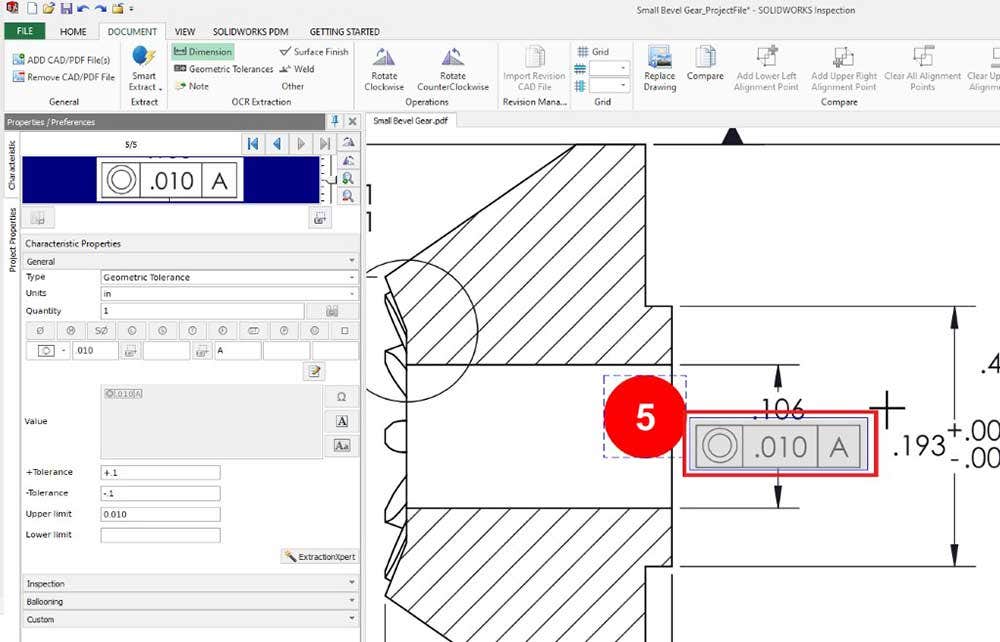
When ballooning drawings in SOLIDWORKS Inspection, the nominal value and tolerancing are displayed in the Characteristics tab. This allows easy verification of accuracy and manipulation if needed. Once captured, the nominal value, tolerancing, min/max values, and character ID are recorded in the Bill of Characteristics within the Table Manager.
This operation is achieved by selecting the Dimension tool in the Document tab and box-selecting the inspection-required dimension. Box-selecting the next selection automatically finishes the current operation and switches to the next dimension requiring inspection, automatically ballooning and numbering the drawing. This simple switching from one characteristic to another allows for streamlined population of the Bill of Characteristics.
Step Four: Exporting the FAI Report and Ballooned Drawing
Everything captured in SOLIDWORKS Inspection is neatly compiled into a standard and editable Excel spreadsheet template and the drawing is exported as a standard ballooned PDF drawing.
To publish the FAI Report, go to the Home tab and select Excel from the Publish category. When selecting Excel, you can choose from the standard templates, or pick a custom template to use. To produce the ballooned drawing in PDF format, select 2DPDF from the same area.
The FAI Report templates are Excel and can be modified meet your requirements. If you want to know more about customizing these templates check out this in-depth three-part SOLIDWORKS Inspection templates video series.
Here is a free AS9102 Excel template to use for your FAI reports.
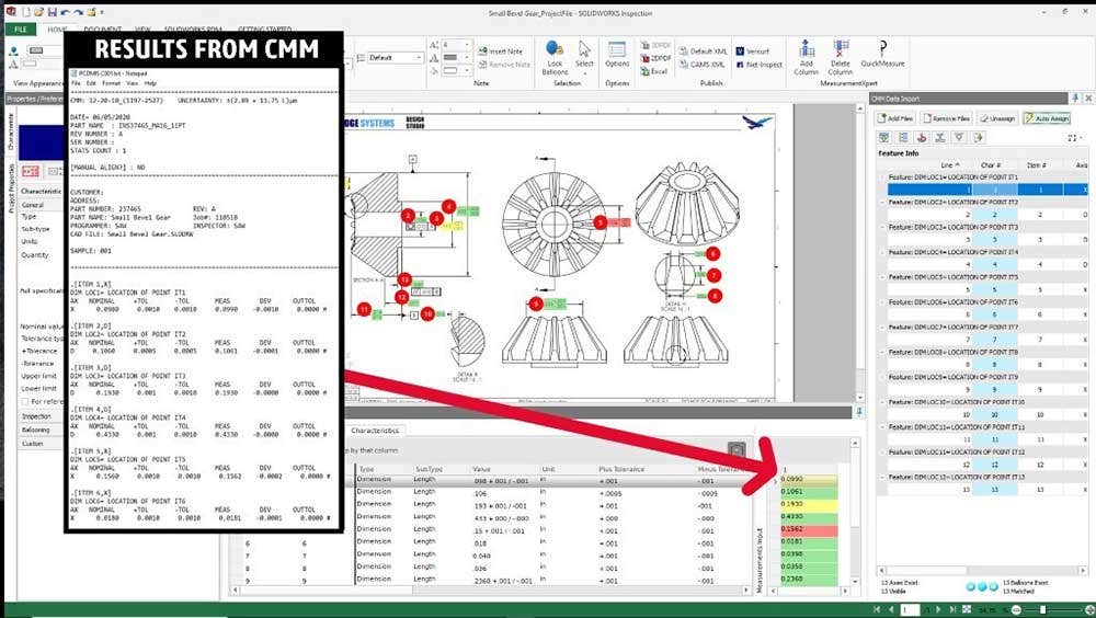
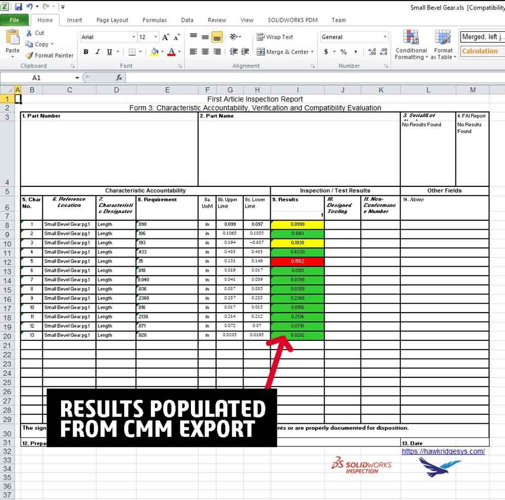
Bonus: If you use a CMM, SOLIDWORKS Inspection Professional will automatically populate the result data directly into the FAI!
All major Coordinate Measuring Machines (CMM) are supported. CMM work by analyzing the manufactured part and outputs specific measurements into a standardized text output. SOLIDWORKS Inspection Professional imports these files and automatically fills in the result data. This eliminates the need to manually enter results into the Excel FAI Report.
SOLIDWORKS Inspection works both outside of SOLIDWORKS for PDF drawings and directly within SOLIDWORKS for native drawings. If you use a CMM, SOLIDWORKS Inspection Professional will automate the entire process from ballooning to result entry. No matter your manufacturing inspection needs, SOLIDWORKS Inspection will help automate the process and eliminate human error.
If you have any questions on SOLIDWORKS Inspection, feel free to contact us at Hawk Ridge Systems for more information. Thanks for reading!


