Innovation starts with someone asking, “What if?” or “Why not?” Answering these questions is often impractical with physical prototypes or hand calculations, not to mention the necessary time and cost. Hawk Ridge Systems knows that simulation provides the most value in guiding design decisions and that’s why we offer complete CAD-integrated solutions for testing a concept, optimizing a design, or correcting a real-world failure. In this webinar, see how meshing plays such a pivotal role in your structural analysis of your design.
Making Sense of SOLIDWORKS Simulation and Meshing
Video Transcript
Introduction
Welcome to today’s webinar. Today, we’re gonna be speaking about SOLIDWORKS Simulation and discussing some of the considerations for meshing in that finite element analysis tool. My name is Glenn Whyte, the director of technical sales here at Hawk Ridge Systems and I’ve been working with the SOLIDWORKS Simulation tool for about 12 years now.
You know, I’d love you to ask any questions you have or any points of clarification. Our topic today – meshing is a huge topic. We’re only gonna be able to cover some core elements of it and some tips and tricks that I’ve prepared for you guys. If there’s a particular question you have, I’d really encourage you to use that question panel. There will be plenty of time for us to, to dig into some of your specific problems or questions or things that you want clarification on.
And before we jump into the content, my last housekeeping element is to just check through a poll that you guys are seeing and hearing. So we’ll start with seeing. If you can see a poll on your screen, you’ll be able to tell me if you’re able to see or if you were able to see my screen. We have a non-unanimous, success there, so that’s great. And then, just a question about my audio and, you’re free to let me know any feedback you have on that. And that is also coming in really positive. Okay, so I think we’re ready to go.
So as I mentioned upfront, today we are looking at the meshing elements of SOLIDWORKS Simulation. Again, my name is Glenn Whyte, one of the engineers here at Hawk Ridge Systems. Now, just to put this in context, here at Hawk Ridge Systems, we’re primarily known as the SOLIDWORKS re-seller. But SOLIDWORKS these days go so much deeper than just be CAD tool. You know, there are tools for electrical design, PCB design, there’s a data management suite, technical communication tools, composer inspection modeled by step mission.
Analysis Tools
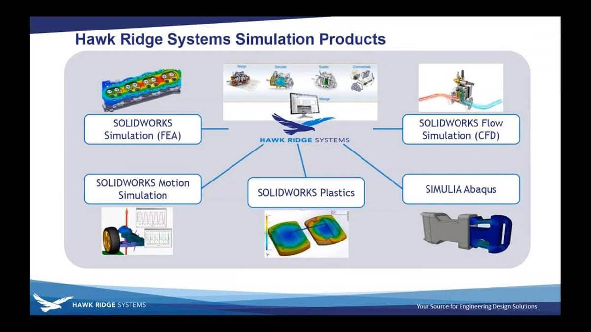
On top on that, we also carry CAM works and the new SOLIDWORKS CAM product released in 2018 as well as a 3D printing tools, Markforged, and UnionTech. But, we’re here talking about analysis today. So if we dig into the analysis suite, we’re really got five different analysis technologies that we feature now. A SOLIDWORKS Simulation is our designer level, structural analysis tool. SOLIDWORKS Fluid Simulation is a really powerful computational fluid dynamics or a CFD tool. Um, SOLIDWORKS Motion analysis, kinematic analysis or assemblies based on the ADAMS solver.
SOLIDWORKS Plastics is for injection molding and Abaqus- SIMULIA Abaqus, as well as some other higher-end analysis tools, is expert level, structural analysis for complex problems, the tool we brought on board, several years ago. But what all of these things have in common for the most part is that their design validation tools, design for all users. You don’t need to go get a PhD in FEA or CFD to correctly apply these tools and get valid answers. They are all, to some level, directly integrated into SOLIDWORKS. So if you make a design adjustment, there’s a very smooth, quick process to analyze the effect of that design adjustment.
And here at Hawk Ridge Systems, we’re a single source solution. It doesn’t matter what analysis product you have, you give us a call at the same line you do for technical support for your CAD system. We provide training. We provide consulting services if needed. We are a one-stop shop for your analysis needs. Just drilling into the structural analysis a little deeper, there are several packages available. The SOLIDWORKS Simulation suite, starting from fairly straightforward stuff on the left to more complex non-linear and dynamic analysis on the right, and even further to the right the SIMULIA Abaqus tool, one of the two SOLIDWORKS that that has.
Meshing
But, what are we talking about today? Today, we’re talking about meshing. Meshing is a fundamental component of everything – especially analysis tools. For a tool like SOLIDWORKS Simulation, it’s a fundamental component of every single analysis. No matter what type of analysis you’re doing, if you’re doing structural analysis in SOLIDWORKS, you’re doing a mesh, whether it’s exposed to you or not.
And meshing is essentially just a, you know, the alternative term for is discretization. It’s the process of breaking down real 3D geometry, for the most part, into a consistent shaped element that we can perform stress calculations on. And in SOLIDWORKS Simulation, we have three fundamental element types: triangles- triangular shell mesh, the thin parts; beam mesh, so two node line element or things with a constant cross-section, Wildman’s, those sort of things; and for everything else, solid, the tetrahedral mesh.
Scope of Elements
We limit the scope of the elements available to ones that we can provide really robust meshing algorithms for. There are pros and cons of different types and other analysis packages like Abaqus, you’ll find brick/hex elements. You’ll find a variety of different items. Everything in SOLIDWORKS is a tetrahedron, that’s solid. So we’re really gonna focus in on the SOLIDWORKS Simulation, tetrahedral elements for the most part in this conversation just to narrow the scope of what we’re talking about today.
Tetrahedral Mesh Element
So that tetrahedral mesh element, by and large, when we talk about this, we talk about the element we’re using in SOLIDWORKS. It’s the one on the right, the high-quality element. This is the default element that is applied to SOLIDWORKS geometry. You try and run an analysis on it. It is the second order element, so it has a parabolic edge, right? So they’re not straight lines, they can map to curve geometry and it has 10 nodes: four nodes at the corners, and six mid-side nodes.
Degrees of Freedom
And each of those nodes has three possible degrees of freedom, it-it’s freedom move in three translational directions at each position and so we say it has 30° of freedom per element. That’s basically how many stress comes – displacement calculations are being performed per element. Like I said, it’s the default. It’s the one you use if you don’t go mess with anything. There is another version of this element in the software. It’s labeled as a draft quality element. You’ll see a checkbox in the meshing window and I’ll point it out we get there.
This is the first order version of that element, has straight sides so one map to curve geometry, has four nodes only at the corners and it only has 12° of freedom per element. Now, that means it’s capturing substantially less stress information for the same size of the element, but the counter to that is that it solves really quickly. So I, typically, use the draft quality element for testing purposes. I wanna see if I’ve got the right restraints in my model. I will use that draft quality element just to fail faster or make those mistakes more quickly.
Tetrahedral elements overproduce stress and bending or underproduce, you know, different things, most of the time. The tetrahedral element is being referred to there as a first-order element like this draft quality element. To be honest, they’re pretty bad. I would not take the results from a draft quality element and show them to anyone. But, some great studies out there that show the majority of situations that high-quality second order tetrahedron is gonna give you a result within an acceptable accuracy, you know, the vast majority of the time.
And that’s really why we picked it as our core element in SOLIDWORKS Simulation. There are very good meshing algorithms available for the tetrahedral element. If you can’t map it to your model, you really can’t do an analysis. So the algorithm that you use in the way the software applies that is really, really important.
Mesh Creation Algorithms
And in SOLIDWORKS we now have three mesh creation algorithms. There’s one we call standard, that’s the one we’ve had forever; curvature-based which we introduced in about 2008, so it’s been around for a while, which looks at the local curvature of the model and scales the mesh to match; and a blended curvature model, which is relatively new. So let’s, explore this based on a piece of geometry and I got to admit that this geometry has been selected solely to be hard to mesh. It is a little artificial but it will do the job.
And some of the things that make it hard to mesh, we’ve got some very narrow sliver surfaces. If you’re getting to hear there’s a lot of stuff going on and these holes for the regular spacing between them, and some cross through, just creating a whole bunch of, you know, narrow gaps and different things.
Static Stress Analysis
So if you create an analysis, you go to simulation and create and you study. Let’s do that. So that’s static stress analysis. We go to create a mesh. First of all, in this advanced section, you’ll see this toggle here turn on the draft quality mesh. If you leave that off, you’ll get the default high-quality mesh that’s gonna give you good elements, uh, good results so that’s fine.
So now, we’ve got these three options here and the software is gonna estimate a default size based on- from the general size and volume of the- of the object.
The standard mesh, in essence, is gonna look at every single face in the model. So that’s a face, for example, and try and map the 3.6 or millimeter element to it, in this case, this has a radius of half a millimeter. That face can’t fit that element. It will try and skew it within the tolerance, it will try and make it fit. We can certainly map two faces that are smaller than this value and, obviously, we have control as well. But at some point, if this face is significantly smaller than this value, it’ll just give up and say, “I can’t.” Right?
Curvature-based mesh
The curvature-based mesh is taking a slightly different algorithm. It’s looking at, the local radius whatever it has and tracks- based on that local radius trying to apply a cell size that’s somewhere between this top value and this bottom value. So you can see immediately we’ve got kind of twice the scope where we’ve got a much wider scope and it’s trying to map eight elements to a circle. Right? As you can see it’s curved around like this so we’ll try and map two elements across that. It’s a good rule of thumb.
The blended curvature-based mesh is kind of an alternative to that. It still looks at the local curvature of things but will try to do a better job of smoothing, big broad areas to give you less mesh overall. So I’ve taken this geometry and I’ve tried to mesh with all three of those approaches. So the first one here, when I tried the standard mesh and I hit run with the default value, it fails. It says, “I can’t do anything with this geometry. This is no good to me.” Right? Rubbish.
In order to get a valid mesh on this model, I had to manually go through the trial and error and apply a local mesh refinement to 133 unique faces. I also had to manipulate the global size down a bit smaller just to even get it to a two-millimeter general size, but I got it done. And so what you’ll notice for this particular mesh is those controlled areas is a very regular even size.
See these ordered rows? And then as we get into the areas where I had to refine, you’ve got a bit of a transition going on in those zones, but that’s all being applied manually. Otherwise, you’d get a mesh-like you’re running analysis on this now. With the curvature-based mesh, I just lifted up the default and hit mesh. With one click, I’ve got a mesh. You see the variance here? You got a big, broad curvature here, and these are big cells.
I’ve got, smaller cells around here to match this very thin piece of geometry up on the top here without any, modification or adjustment. Now, this doesn’t mean this mesh is good enough for an accurate result, we’ll talk about that in a minute. But, we did get it done with that curvature-based mesh. It’s a lot more flexible. And the other one I tried here was the blended mesh, which has very similar settings. you know, my take away from this one is it’s just a lot more organized. Right? It’s kinda got the organization of the standard mesher and these nice regular, you know, adjustments.
It’s kinda made a mess of these holes, but that’s fine. We have some of the curvature-based elements, it’s kinda somewhere in the middle. There are considerations on how long it takes and how much mesh it generates. So if we compare kind of some of these fundamental, parameters, starting with the standard meshes, the big call out here is that it took me 35-ish minutes to poke around and figure out which bases needed to be meshed with me going through and trial and error processes to get all those mesh controls in place.
Standard Mesh
A standard mesh has very limited use of multiple calls on your CPU. That takes about 30 seconds- 36 seconds to process that mesh. And with all that mesh control in, that was 110,000 cells. The curvature-based mesher is very good at using multi-processor computing. It runs in 16 seconds, one click, it’s done. So my total cycle time is the time it took me to wait. 71,000 elements at the default. ‘Cause it’s only refining mesh where it needs to, where there is a high curvature.
It’s slightly high up the percentage of highly distorted elements, but I could go fix those if I wanted to. And then the blended curvature, I kind of think in this as my really big hammer if I’ve got a really challenging meshing problem. It doesn’t use multiple calls very well, so it is slow, the slowest of the group. But, it will generally produce the least cell surf in a very big complex problem. I mean, you’re gonna get a smaller result, a smaller number of cells. That may not be good enough for accuracy, but it is one of the best.
My recommendation to you is to select one of these and make the curvature your default. It’s more efficient and generally, does a pretty good job, but save the blended curvature for if you’re really having a tough meshing problem. Again, it conflicts to battle, take you longer to get that mesh done, but it might keep your cell kind of down.
Now, you know, traditional FEA will always tell you that a compatible mesh is needed for accuracy or it’s the best case for accuracy and it is certainly the best case. It only applies if the parts are bonded. If this is a no penetration, a sliding contact it’s gonna be incompatible by default. So what do we mean by incompatible? Well, in an incompatible scenario which is just that same spot the two parts mesh completely independently. There’s no correlation between those things. If I was to hide the top part, the bottom part is gonna look exactly the same under the component as it does everywhere else.
Traditionally, this would be considered bad or non-desirable and in this case, we have a very large difference between the sizes. This is really not desirable, but in this scenario, when we solved this analysis, an incompatible meshing will apply some secondary calculations, what we called mortar bonding calculations, to create a match between those mesh components and those calculations have got better and better over time and are better now than they ever have been. So they just proved that out a little bit.
Compatible Mesh
I’ve actually run these analyses. Right, so this first one is a compatible mesh, okay? I’ve got a very sharp point on this. I just got a nominal load pushing on it. You can see the stress distribution through these. If you’re ever looking at stresses between two components, there’s this option that SOLIDWORKS loves to turn on by default to average the results across the boundary for the parts. That’s not really real, kind of gives you this and in the cell, the high spot is kind of jumped up off the point, that’s not where it’s occurring. Generally, I recommend turning that off so that it’s not doing an averaging calculation across that interface.
So that’s a compatible mesh. It’s probably the best case. You can run an incompatible mesh and you can run the analysis. It’s gonna do a pretty good job with one caveat. I’m just gonna have to grab that model again. The caveat is there are two options of what style of incompatible analysis you would incompatible mesh. I would recommend not using one over the other without trying both of them.
So the option that I’m referring to lives here, right, in the properties of the study, in the silver options under options, yeah, incompatible bonding options. The default is this one called automatic, which will either use a, basically, a terrible calculation or good calculation or that merging of nodes underneath that, uh, that area, if you pick automatic, 90% of the time, it uses the accurate one, but sometimes it’ll go back to the simple one and you will get the wrong answer, so that’s one that I always recommend setting to more accurate. It says it’s slower, but, uh, the results are pretty bad, so what’s the point of a fast result that’s wrong, right?
So this is the more accurate results here. You can see, you should get a little bit of a different result. It’s not as good as the compatible. We have big, big differences in mesh size, so I certainly wouldn’t recommend that role, but it’s relatively smooth and it concentrates the peak load corner, the simplified, incompatible bonding. You know, it has these weird spots in places where they shouldn’t be stressed. It’s just not good, so I would strongly recommend staying away from that simplified calculation. I think it’s only still in the software for legacy support reasons that if someone wants to mimic an old calculation, but it is something to steer away from.
Incompatible Bonding
But the question that comes up here is why incompatible bonding at all, you know? Why is that even an option? And the reason it’s an option is that only having a full swing compatible bonding can sometimes impose a limitation. That means, you cannot get a mesh to compute, right? So, basically, when we’re meshing this as a compatible model, it’s got a mesh this is the zone that’s not underneath the object and then separately meshed the zone that is underneath. if I was to create like a very small silver face here, my chances of getting a mesh element on there are probably pretty poor. Whereas, incompatible doesn’t care about that at all.
In fact, you’ll notice that one of the first options for a failed mesh is to just try the thing again and with incompatible mesh to see if that makes a difference. In most real-world scenarios, the incompatible mesh, the calculation does a pretty good job of not being accurate. And the other thing, compatible mesh requires that all the mesh- components of mesh at exactly the same time. I can’t do anything sequentially. Whereas, if I’m meshing things incompatibly, as we’ll see in the next example, I can take a sequence through where I mesh some parts and adjust others without having to re-mesh the whole thing. That can be a good little processor.
So let’s say that incompatible mesh more likely to create a successful one, but just know you’re doing another calculation. So we’ll keep going here. The other thing that’s worth considering when you’re looking at an assembly is to think about the types of geometry you have. When SOLIDWORKS meshes things or when you create a study with one of the assembly or multi-body part, it does some things out of the box. It looks for special geometry cases. It sees sheet metal, it’ll create a 2D shell mesh. It will treat it as a surface and will do that automatically. If it sees surface geometry, it’ll make that a shell mesh and throw it into your model.
This can be problematic if you use surface geometry to maybe build up the shape of your part but if it was kind of construction geometry, you’re gonna want to delete that out or exclude it from the analysis. If it sees weldment it’s gonna throw a beam mesh on it and everything else it finds it’s gonna make it a tetrahedral mesh. But none of these choices are permanent, right. They’re all editable. So I’ve got this kind of Frankenstein part here that’s got a block- two blocks sheet metal a surface that’s only 2D. It has no thickness and a weldment and they’re all kind of jammed together.
By default, the software says, “Hey, I found some sheet metal. I found a surface and somewhere in here, I found a weldment and the icon reflects that.” Weldment and surfaces are simplified representations, but I can right-click any of them and say treat as solid and it will mesh and analyze the true 3D geometry of the part. It is pretty smart. When it does the sheet metal, it’ll automatically recognize contact between components. I’ll mesh this one. These two parts have a little bit of an offset between them because it’s put bad at the midplane, but that contact will be respected and will do that automatically.
Same goes for the weldment component, which is nice. But, why do we take advantage of things like shell and beam mesh? It’s because they are more efficient. If I was to mesh this Frankenstein geometry with all solids, so everything has meshed to its true shape. I’ve got a mesh element across the thickness. It’s highly distorted, so it’s probably not a very good result. Same goes for this guy. It works out to roughly twice the elements than if I use, you know, shells and beams, which is what I’ve got here.
One of the downsides in shells and beams is that you’ve got these simplified representations of the geometry, but a few years ago we got a switch to map the stress and displacement results to a representation of the real geometry and so these things now have a thickness and so it can be better for communicating your result. But I would say to always review your model for things that are particularly shells then constant thickness. Put a shell on that and, you’ll see big improvements in performance and often in accuracy as well.
This is probably the most common issue before the curvature base mesh was as strong as it is now. It was a bigger issue but the most common complaint we’d hear from the technical support is I tried to mesh my model and it didn’t mesh, what do I do now? We have a little sample model here. Let’s get to this one, right. I’ve got things like nuts and bolts, one of the modeled in true shapes.
I’ve got the hexes on my screws still in place. If we hit the mesh on this model with the standard mesher, I get 11 parts that fail. In fact, let’s do exactly that. Standard Mesh, a standard size hit Mesh, about 56 seconds later, I get 11 parts that fail. Now the software will guide you through- already at red is something to fear. So the software does have an approach that will guide you through, a correction to that. I like to know how to do it myself before I take advantage of any of those regular tools so this is the approach that I advocate before you activated they need the automated tools to help you out.
You start by checking your model. Here are my 11 things that failed. We’ll talk about the diagnostic in a sec. Right so there’s parts just missing, they didn’t mesh. Check the model. I like to go to the evaluate tab and do an interference detection. The software will mesh interference, but sometimes it’ll cause it to fail and if you’re running in the analysis, any interference is not intentional. You’re trying to model a situation that doesn’t exist in real life. There are some situations that are intentional, like shrink fit or rings or things like that and otherwise, I like to know if I have interference so I run that.
The other thing I always do is evaluate and a consistency check. Do I have valid solid geometry? If I brought this over from, you know, Creo and it didn’t fit properly on import, it will never mesh. You can troubleshoot it for years and if you don’t have an actual solid, it will never mesh. The other question you have to ask is do you even need this thing? You know, do I need the-the Phillips Slot on my screw there?
Is the thread on my bolt important strength is an object or can I represent it with say a bolt check? But if I’ve decided that it is necessary, what I typically do is I grab the thing in the knuckle here (one of the things that failed) and I pop it open in its own window. I create a study, new study and I try and mesh the thing on its own. I might need to pick an alternate size, but this thing meshed quite successfully with the default size of nine millimeters. I know that with no other parts at play, this thing will mesh with a nine-millimeter mesh. Now I take that information back to the assembly.
And I say, “Oh, well, if I apply a mesh control and a little trick here, if I pick a face from the screen, I’m only going to get that face of the object but if I drag a box around it from right to left, I get the whole part. And so it’s gonna mesh the entire body and the final resolution and does that get it done? Let’s find out. The situation when it won’t work is if the connection between parts and the requirement of a compatible mesh is creating an interface that it’s unable to mesh but I believe that adjustment to that knuckle was good enough to get the knuckle done.
And so then you can then repeat the process for all of the parts that failed, right? So then I’ve got moving that control down to nine millimeters was enough to get that done. And so if you’re really trying to be very regimented, that’s the process there that you can go through. Around the screen and like this will always work. It might take some time a being very diligent and working through this process of applying mesh controlling and improving it will-will always work.
I will just undo that change so if I do apply mesh control and remesh the whole thing, it maintains compatibility. So that’s important. We’ll just let this go here but the software will also offer you a mesh troubleshooting diagnostic. Right, the first thing it will say when it fails is, “Hey, do you want to try and fix this?” If you use this approach, what it will do is that it’s going to offer up some options here for how to fix it. You’ll say, “Hey, do you just want to try and compatible Mesh everywhere? Or do you wanna add some mesh control, if you mesh control from this interface it will only adjust that individual part and it will force an incompatible mesh.
If you use this diagnostic and you say, you know what – I just wanna modify the knuckle, right? Right wherever it is, but I just wanna put mesh control on this guy. Now it’s gonna just remesh this guy. It’s gonna do it incompatibly which is great if we’re getting it done. But you have imposed that incompatible mesh now. Okay, let’s move on. We are running a little long here and I apologize for that, but one more key point that I wanna cover. And that is, everything we’re talking about so far is about been getting a mesh onto a model.
And you know, we looked at some basic things about distortion and those sort of things. But everything we’ve talked about today has been about getting a mesh onto the part. We haven’t yet really talked about whether that mesh is good enough for a good result. And the fundamental of FEA is that, if your mesh isn’t good enough, your result’s garbage. And, you know, a lot of the expertise you build up over time has been able to very quickly judge based on a given scenario, that you might’ve seen before, whether you’ve got a good enough bench.
But if you don’t have that experience yet, you can fall back on some into some routines to always make sure. And this is the ultimate trade-off, right? We could all throw 10 Million elements on every model we do and almost guarantee a decent answer, but there’s no sense in waiting four hours for a re-analysis run. If you just, maybe doing some early stage investigation. So, I’d encourage you to be smart about the purpose of your analysis. Got this simple analysis here, good bracket under some loads. In there, that’s one or two.
Analysis
And I can go run the analysis and I’m gonna start off here. Run it at the extreme level, if I can run this analysis with a fairly coarse mesh, a couple of distorted elements, it predicts a peak stress of 107 megapascals. Greater. There are a couple of things I look for. This result looks blotchy. It’s got these weird kind of, stripes to it. That’s never a good sign. But in general, once you got a result from an analysis, you should always try to improve it or try to validate it. So, I would generally go in and refine the mesh a little bit further.
Like this case, I’ve made it twice as dense and run it again and see if my 107 megapascals are holding up. And in this case, it has jumped up to 114. That is rough, a 7% increase. Seven megapascals increase, it’s about 100– so, 7% calling it. That’s pretty significant. So, we try again. Create another mesh and then we go half as big again. We run it again. That’s what’s taken longer. Now the processor. But in my head, whether I do this formally or not, I’m always questioning the result and I’m always trying to get a couple of data points to prove to myself, kind of, how stable my results is. Whether I do it formally or not, I’m always trying to build an internal table that looks like this.
The first column is the mesh size. The second column is the degrees of freedom. The number of elements in this is a number of stress calculations in this model. I then look at results. I can look at the displacement result, which will not change very much. The distortion of the model is not very meshed sensitive, but stress is. It’s 20 megapascals. 20% across these tests. The solution time goes from two seconds so I don’t even know what that is. In minutes? I did run out of memory in this top one. To the silver, I’d selected, um– there was too much memory in my system.
This whole wanted to switch me to a different solder that would have been more efficient, it would have been a lot faster, but just for consistency, I stuck with the same solder. So if you put that out, horizontal access there’s degrees of freedom but it collects this stress, you often see these curves that have this kind of knuckle to them always. Right. Where, you know, between 100,000 cells and 700,000 cells, and kind of variance of like three or four megapascals. 3% or 4%, that variance is probably going to be less than a bunch of the assumptions have made in putting these analyses together.
So the lowest model that I’m happy with that gives that result, is my most efficient one. That might be the one that I try some different design alternatives on. Somewhere down in here. Then I can use this one, but it’s gonna take me longer, regeneration. On this particular example, I’ve meshed the whole model. A way to be a lot smarter is instead of meshing the entire model to a higher degree of resolution, it just meshes the areas of high stress, or high-stress gradient, to be more accurate.
So I’ve used the mesh control tool to drill in on these faces. And, you know, with that result, I can get a very similar result to this, with this much mesh. Just by localizing that.
Other tools that you can use to help yourself prove that you have good results and the best quality parts. There is a result in the mesh quality called era. It’s not an absolute era. You can’t take it from the bank and say, “I’m two megapascals off here”. It’s an indication, but you will see the stress result somewhere right here. Energy non-era.
Now, it will point to areas there are just sudden elements where there might be error, but if those don’t cross on to a high stress. Maybe you don’t care. Like this component is going to break here. If I’m 10% off up here, it’s still not going to break there, at least for this particular scenario. So take it with a grain of salt. Mesh- employ mesh controllers smart. FDE rule of thumb, we talked about that before.
Two elements across the thickness, two elements around the fillet is always good. There is a tool you can activate in the properties of the study. It’s called the adaptive mesh refinement. I will show you where it exists. It’s under adaptive. I recommend eight adaptive. And what it will do is it will run a series of analysis, remeshing the model after every single instance. So it’s just on one. It’s going to remesh internally. It’s done the second one. Let’s see how many it’s going to do. It’s trying to put one right now. All right, so it’s presenting a result but look at the mesh we get. It’s automatically refined it and see the results. So that’s the technique you will use now. That takes longer.
And the last one here is that I think the tool called the train tracker. What train tracker does is basically, every time you run an analysis, it saves the results out and kind of stores that data. So I ran my convergent study with train tracker on, and it’s kept five iterations of my model, tracking across those five iterations how the stress change.
Okay, that’s most of what I wanted to cover. Uh, sorry that we run a little along there, but I would like to just finish up by highlighting some of the things that we have available in terms of analysis assistance.
If you want to go deeper in SOLIDWORKS Simulation, please CONTACT US or GET A FREE TRIAL TODAY!


