The product development cycle has been changing dramatically due to additive manufacturing. From gathering measurements, designing optimal parts, and rapidly creating parts for testing; additive and traditional design tools are complimenting each other to make going from idea to physical quicker than ever before.
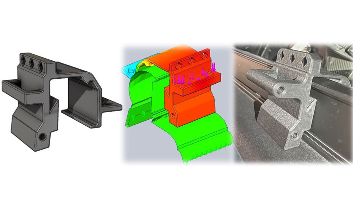
To discuss how these changes are improving design cycles, we developed a case study that uses a combination of additive technology and CAD software to create and modify an aftermarket clip to attach to a truck bed. Two of Hawk Ridge Systems engineers discuss which tools were used and thought process that went into the development of the case study, knowing different technologies will be used.
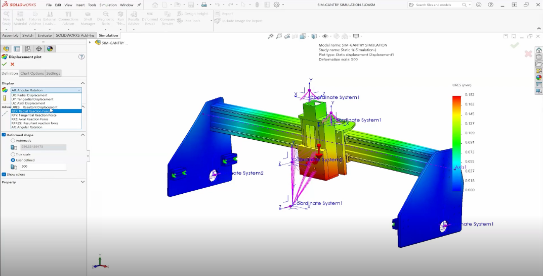
This case study goes over the entire workflow for the product development and how we move from one design tool to another. From 3D scanning the car, designing the clip, printing a prototype, and optimizing the part further using SOLIDWORKS Simulation.
The functionality of the tools and how they are setup will also be discussed. Providing a deeper understanding of how we can use these tools to their fullest and setting up for future projects.
During the webinar we’ll cover:
• The initial problem statement and limitations we had going into the project
• Which 3D scanner was used to capture the real-world rail needed to design around
• How we created a reference solid body inside SOLIDWORKS from the 3D scanned mesh
• Why the reference body helped design the initial model of the clip
• Printing and testing the clip
• Using simulation to find areas that can be improved on the initial mode
• How a design study can be used to quickly test part configurations and optimize the clip
• Which SOLIDWORKS CAM tools can be used to create additional aftermarket parts
Watch Webinar Now
If you’re interested in how you could use these tools in your development cycle, please contact us at Hawk Ridge Systems today. Thanks for reading!


