For the past five years, I’ve made onsite visits to help customers implement and operate Markforged 3D printing systems. Markforged is known for their continuous fiber composite printing, and the topic of custom fiber pathing – or having multiple settings in different areas of a part – has come up frequently in my trainings. My response has always been that although there are approximately ten different fiber configuration settings that will get the job done in the proprietary software, you cannot write your name in fiber so to speak. I’ve probably told that to hundreds of customers over the past few years, but today I’m here to set the record straight.
I recently discovered a workaround that allows you to create pockets of different settings within your part, so you can in fact write your name in fiber, or have multiple settings in different areas of the part. In other words, you can create a custom conformal fiber path in any geometry you like within your part.
Steps to 3D Printing with Multiple Settings
After discovering this, I thought it would only be right to create this blog to share the information and show everyone how it works. For the purposes of this project, I will be designing and creating a part that has my name written in continuous Kevlar.
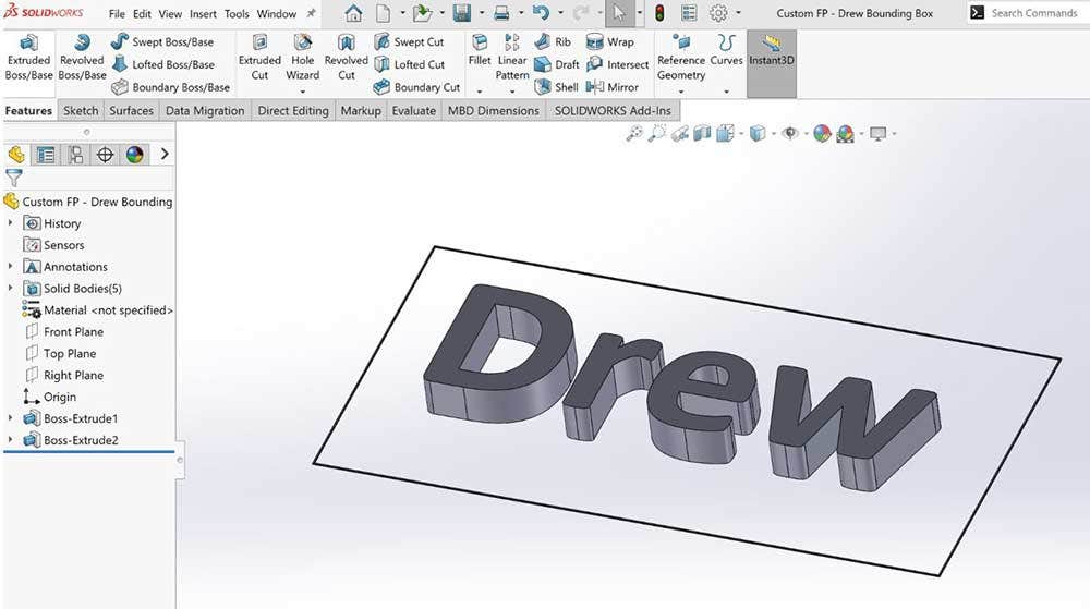
The first thing I needed to do was create the CAD models. First, I modeled a bounding box which will help me align the two parts later on the build platform.
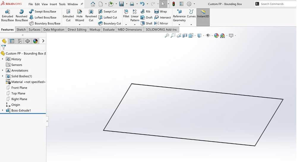
After creating the bounding box for alignment, I then modeled my name and extruded it to the desired height.
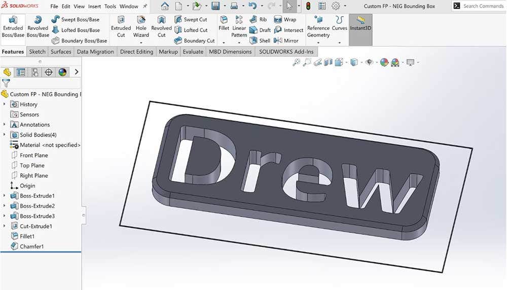
I saved the model as an STL file, and this will act as the first part in my two-part build. Then I modeled a second part that was a negative of the first by extruding a box around my name, and then using the simple Extruded Cut tool in SOLIDWORKS. This created a negative of the first part which I saved as an STL, and this will act as the second part in my two-part build.
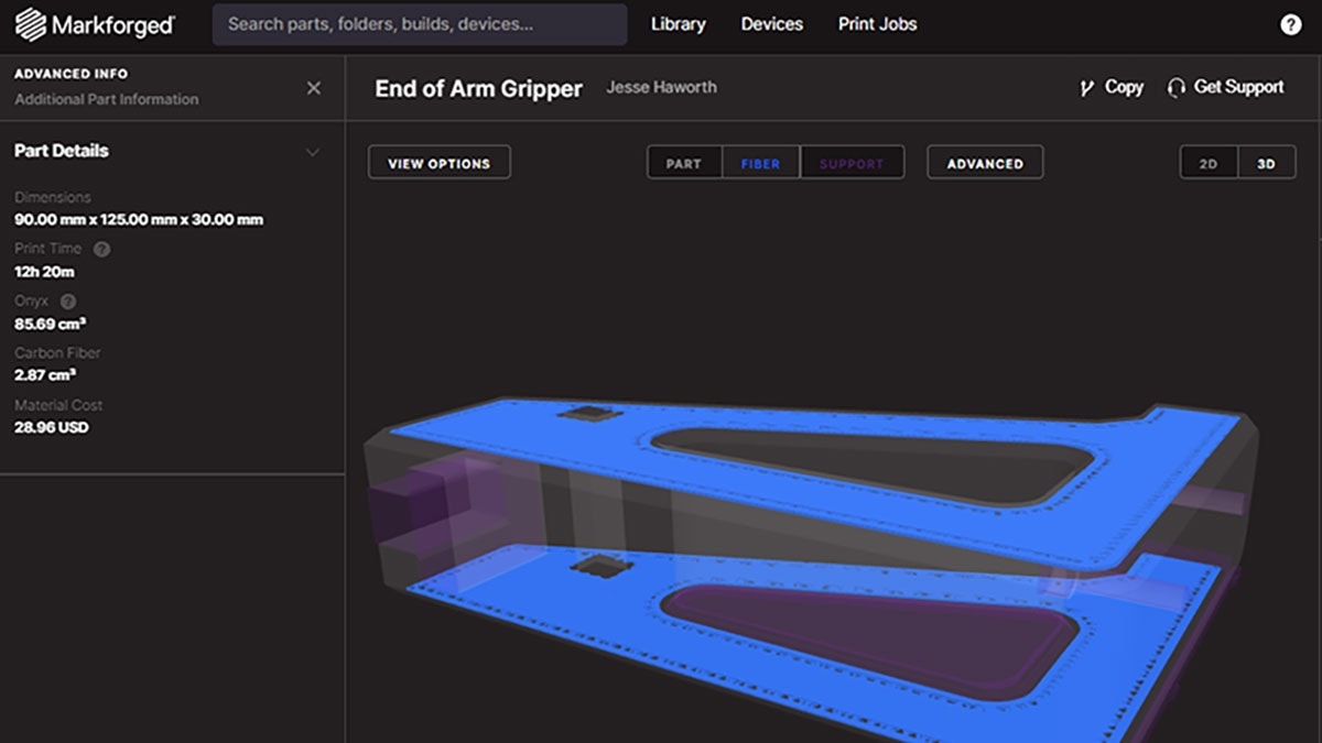
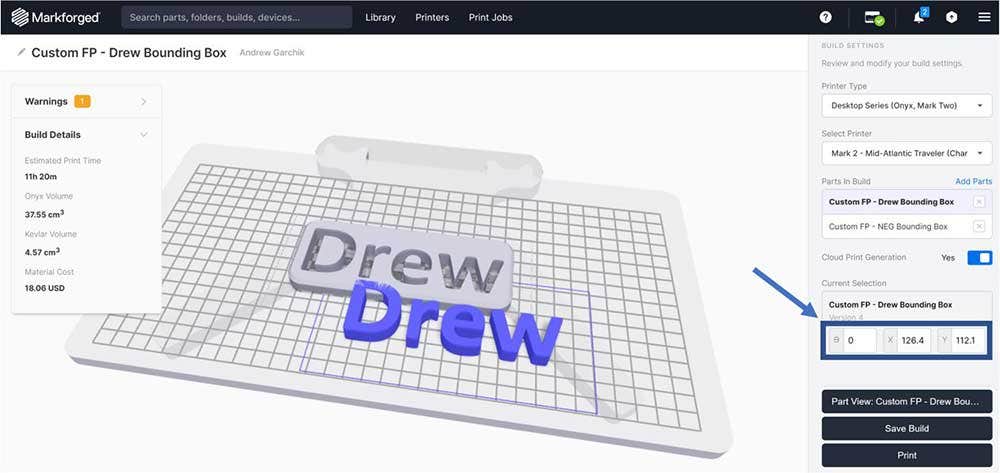
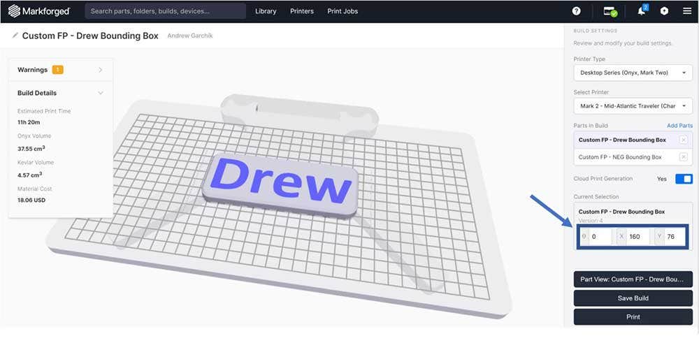
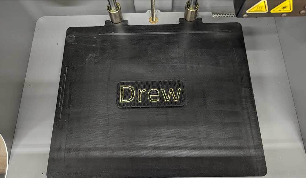
Next, I uploaded both parts into Eiger with the first part set to gyroid infill and continuous Kevlar; and the second part was set to triangular infill and no continuous fiber. I combined both parts on the build platform and entered the angles manually to align them. Because they share the same bounding box, entering the same angles will align them. A pause was placed in the build so that the build would end prematurely, exposing the Kevlar and infill (for you!).
The End Result
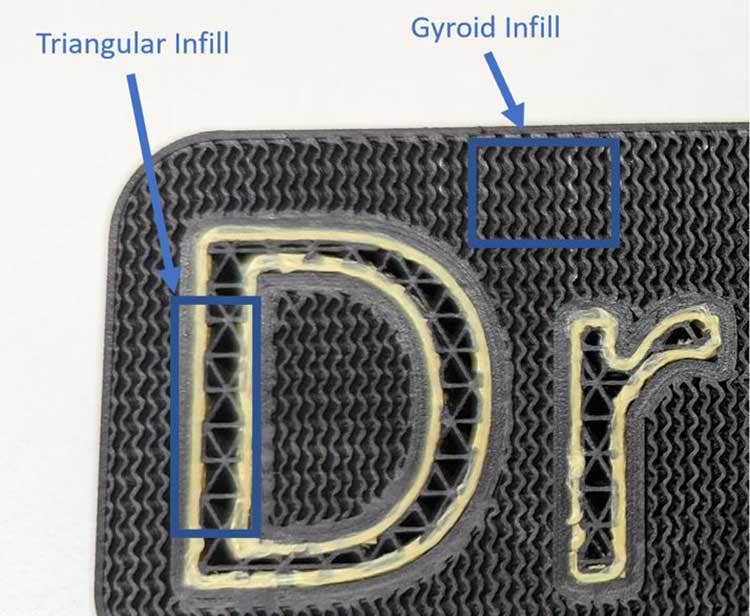
And here’s the result, a part with my name printed in continuous Kevlar.
You can also see that the infill patterns are different: triangular vs. gyroid.
I used this work around for infill and fiber, but it can be used to create areas with any custom settings within your parts. Hopefully this tutorial was informative and helpful for your additive manufacturing endeavors. If you have any questions about Markforged or any of our additive solutions, contact us at Hawk Ridge Systems today. Thanks for reading!