Discover a few simple additive manufacturing practices that can help to enhance your Markforged experience, including:
- A few tips and tricks that will change your additive manufacturing game;
- A look at breaking up and re-assembling larger parts or assemblies;
- And a demonstration of how these practices can impact your parts.
Additive Manufacturing Tips & Tricks
When adapting 3D printing technology into an existing workflow, the first action of many individuals is to print parts that were likely designed with other manufacturing methods in mind. While many parts that are not specifically designed for 3D printing will print without issue, there are several additive manufacturing design techniques that can help to enhance part performance and quality. In the world of 3D printing, modifying part geometry so that it is better suited for printing is known as design for additive manufacturing (DfAM).
Reducing Overhangs and Supports
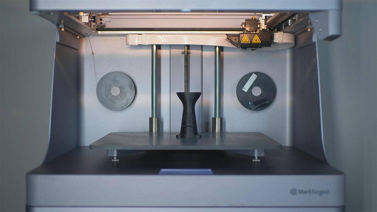
Markforged machines are based around fused filament fabrication (FFF) technology, meaning that parts are built up one layer at a time. Since placing a layer of material over nothing would cause problems, the first few layers of any overhanging feature need to be held up by a support raft. These support rafts are automatically placed by the Eiger software if any overhang is deemed too steep, and are easily removable once a print is complete.
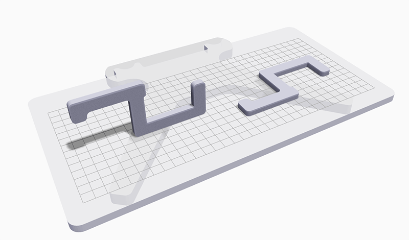
Support rafts are also made of Onyx and are used to uphold any overhanging geometry. The alternating thin geometry in this illustration is an example of a support raft.
Support rafts can increase print time and material usage, however, so reducing the number of overhangs is one of the easiest ways to improve print statistics of a part. A good general practice is to shoot for 45-degree angles for vertical features, which do not need to be supported. Fillets, chamfers and angled designs are all efficient ways to modify features that would otherwise need to be supported.
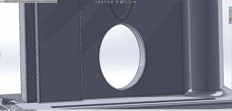
The upper layers of circular features would need to be reinforced by a support raft in order to reduce print issues.
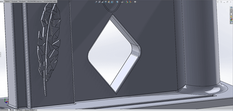
Diamond or teardrop shapes can be used in lieu of circular geometry to remove the need for supports. This is useful for removing the need for supports from hard to reach channels.
Orientation and Axes of Strength
Reducing overhangs is only one part of a larger topic – choosing an ideal print orientation.
Due to the nature of FFF, orienting a part with the flattest surface down will usually result in high quality, functional parts. Before printing a part, however, it is important to identify the following:
- If the part is load bearing, what direction will the forces be coming from, and what types of forces are they?
- What are the critical features of the part in terms of strength and accuracy?
- Do some of the part features need to be printed, or can they be replaced with easily accessible components?
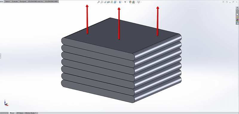
For a better understanding of how part orientation can impact the first two questions listed above, here is a simplified illustration of how a Markforged printer would create features. Since each material layer adheres itself to the layer that came before it, parts will naturally be stronger in their as-printed X/Y direction.
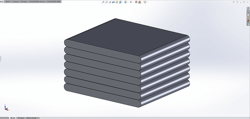
A simplified representation of how each extruded layer is laid on top of, and bonded to, the one that came before it.
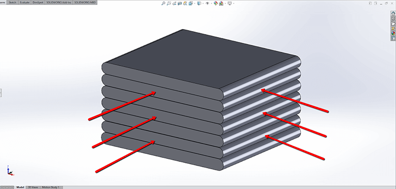
Conformal forces in the X/Y direction of parts will be reinforced by the material properties of each layer.
When certain types of forces are applied in the Z direction, parts are typically only as strong as the interlayer connection.
The unique ability of Markforged printers to inlay fiber can help to enhance the strength of parts in many situations, but it will still be important to determine what types of forces will be applied to your part, and in what direction they are applied from.
Similarly, features that are aligned to the X/Y plane of the print bed may print more quickly or accurately. This is due to the fact that feature boundaries in these axes will be printed with one continuous tool path, rather than be made up of individual layers.
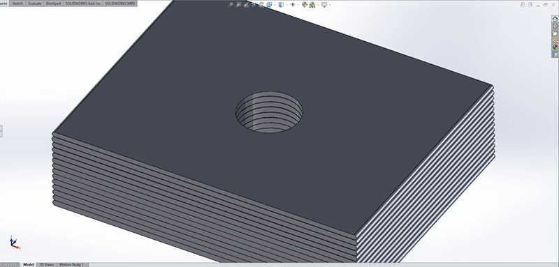
When oriented in the X/Y plane, each layer of this circular feature will print as one continuous toolpath.
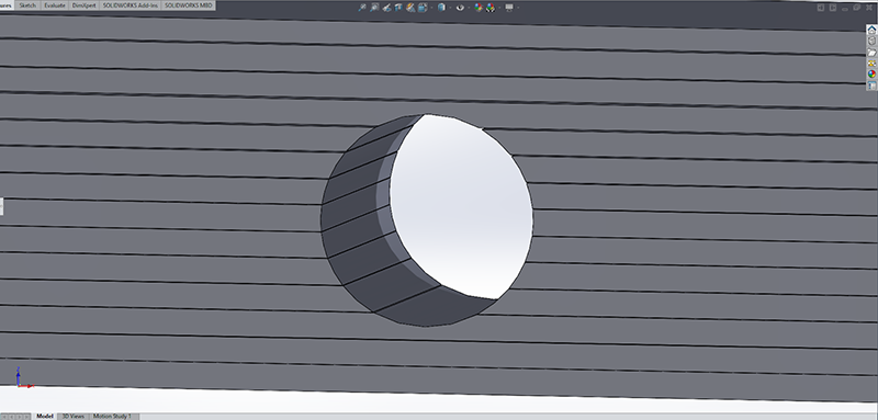
Alternatively, the edges of this same feature would be made up of extremely small layer steps, were it to be aligned with the Z plane.
Assemblies and Multiple Parts
To switch gears, let’s review some options that will allow you to break up and join larger components that may not be ideal to 3D print as a whole.
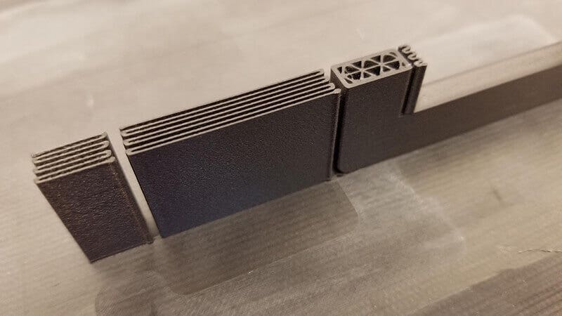
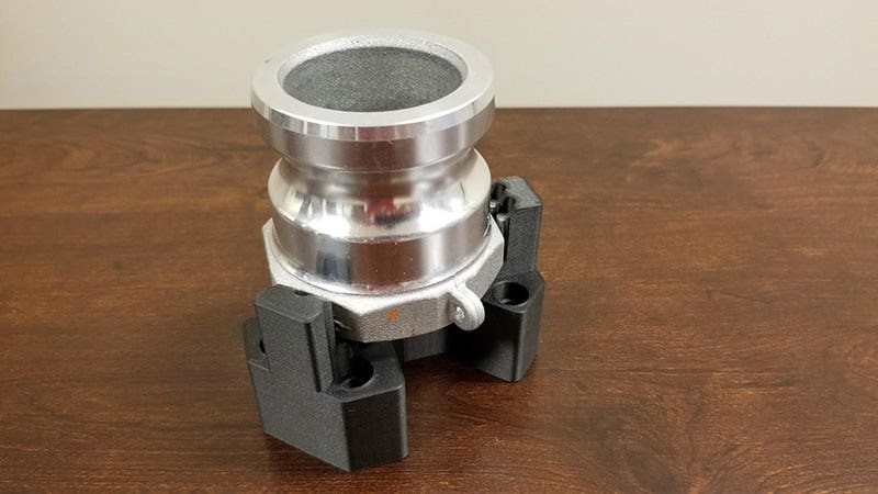
Whether due to part size, strength requirements, or material usage, there are many potential benefits to breaking up larger files into smaller parts. To illustrate this point, consider the carburetor manifold part pictured below:
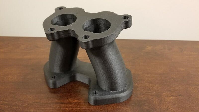
A carburetor manifold intake component, printed on a Markforged printer.
Ideally, both the top and bottom components would be reinforced with fiber. This would give the entire component some added stiffness, especially around the bolt holes. Were this part to be printed as-is, however, it would run into the following issues:
- Overhanging features would require supports, increasing print time and material usage.
- Both ends of the manifold are not mounted in the same plane, due to the angled nature of the part. This means that only one end could be efficiently reinforced with fiber.
To improve print quality and strength, this part could be separated into four separate components, resulting in less material usage and better reinforcement.
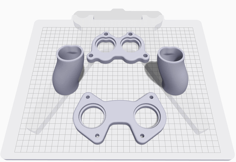
A build picture for each of the carburetor manifold components.
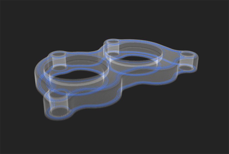
As a separate component, the top of this carburetor manifold was able to lay flat on a print bed, which in turn resulted in more effective fiber pathing.
The components of this particular part were printed for testing purposes, so they were simply joined together after the fact. When designing components to fit together, a 0.08mm gap between walls will typically result in a secure fit. While testing different assembly methods, such as joint types or adhesives, small cutouts of your part can be exported from your CAD software and printed for testing.
Utilizing Easily Accessible Hardware
Utilizing consumable, mass-produced hardware (screws, bolts and nuts) can increase part performance, which may prevent unneeded reprints or component failures with Markforged composite parts.
While Markforged composite systems are certainly capable of printing usable threads, the exterior portions of the threads themselves will still be a Nylon-based material. Depending on the application, printed threads may not perform as needed.
An alternative to printed threads would be to embed nuts into a part via the Eiger “Pause After Layer” functionality. This allows you to set an automatic pause in your print. Use this in conjunction with a pre-designed cavity to pause your print, insert your desired component, and resume the process.
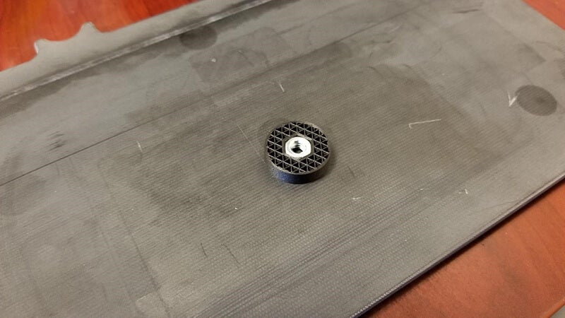
The “Pause After Layer” functionality allows users to easily set a pause point, insert a component, and then resume printing.
An example of a captive component.
Heat set inserts also allow for components to be inserted, but these are typically used for inserts that will be placed on the exterior of parts.
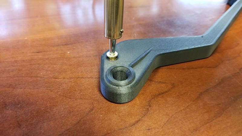
A brass insert being heat set into a Markforged brake lever.
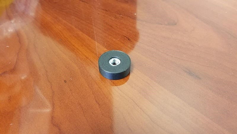
Lastly, dowel pins are another component that can extend the life of your 3D printed parts. Rather than subject the surface of your parts to abrasive conditions, consider using dowel pins to replace any high-wear areas.
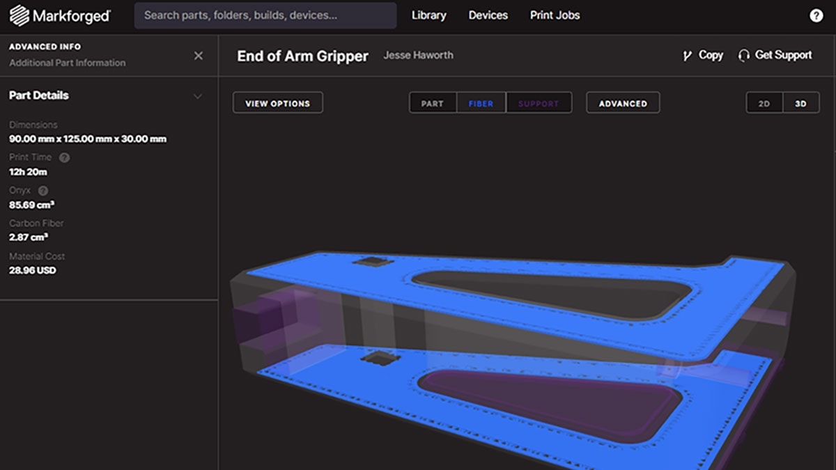
The life of this gripper component is greatly extended by using some simple dowel pins to replace high-wear surfaces.
Demonstration of Best Practices: A Tale of Two Brackets
Let’s take a look at two brackets that were printed on a Markforged Mark Two. Both of these brackets include Carbon Fiber, and all print settings were left at their default selections. In terms of design, they are also the same file, with a thickness of 0.25.”
Once we printed both of these brackets, we performed some weight testing. Note that the goal of this testing was simply to provide an overall picture of the differences between our two brackets, so we did not control some of the variables that are present. The results of these tests showed:
- The first bracket that we tested was able to withstand about 30 pounds of force before failure occurred.
- The second bracket that we tested was able to withstand 60 pounds of force, which was the maximum that our scale would measure. This makes the bracket at least twice as strong as the one we tested first.
Even though both of these brackets were identical in design, the one critical area where they differed was print orientation. As shown below, one bracket was printed vertically, while one was printed on a side.
The vertical bracket was able to hold around 30 pounds, while the horizontal bracket could withstand at least twice as much weight.
To get a better understanding of what made the horizontal bracket so much more successful, we can take an internal look with the Eiger “Internal View” functionality. This allows us to see how each layer will print, as well as view fiber pathing.
The internal view of parts allows us to more closely investigate how each individual layer will print. Carbon Fiber is colored blue in this view.
As previously mentioned, both of these parts were printed with default print settings in Eiger. Inlayed fiber works best while in tension, so by default, Eiger will set a small number of fiber layers near the top and bottom of a part. In theory, this allows loading conditions to place one set of fiber layers in tension, while the opposite layers of fiber are compressed.
Below, you can see a visual example of the loading conditions for our bracket that was printed horizontally.
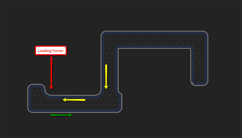
An example of the loading conditions for our bracket that successfully held weight. Yellow arrows represent fiber tension, while green arrows represent fiber compression.
Now that we’ve identified why one of our brackets was more successful, let’s take an internal look at the failed bracket.
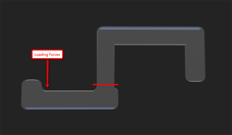
An internal view of our bracket that was printed vertically. The failure point is visualized as a red line.
As was the case with the horizontal orientation, Eiger did place several layers of fiber near the top and bottom layers of this part. Due to the specific loading conditions of this bracket, however, there were no layers of fiber to be placed in tension when forces were applied. When combined with the printing orientation, this resulted in all forces being applied to the adhesive bond between separate layers.
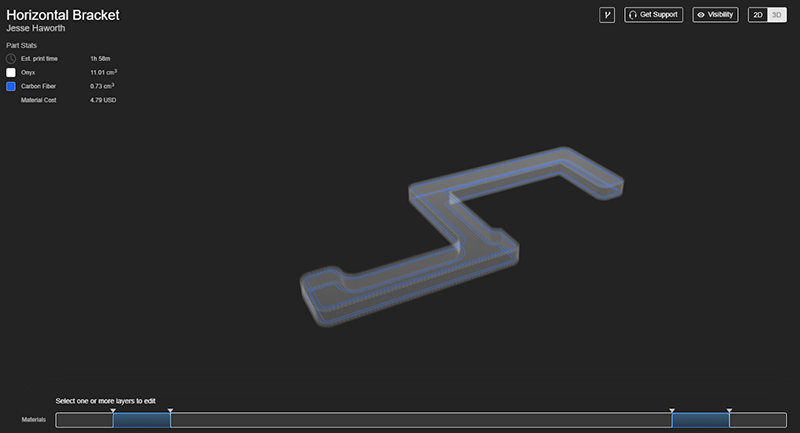
Lastly, it is important to note that not only did the horizontally oriented bracket perform better, but it also printed faster, was cheaper, and used much less Onyx material. Take a look at some of the stats listed below.
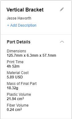
The print statistics for our vertically oriented bracket. Take note of the print time and material cost.
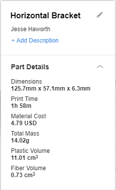
The print stats of our successful, horizontally oriented bracket. With this ideal orientation, the part was much stronger and printed in less than half the time when compared to our vertical counterpart.
The print time increase for our vertical bracket can mostly be attributed to the need for support columns to uphold some geometry. This is a perfect example of why some of the simple modifications mentioned in the beginning of this post can make a difference.
If you would like to see some statistics for your own parts, create a free account for the Markforged Eiger software here.
Stay tuned to our blog for more Markforged content, and as always, feel free to visit Hawk Ridge Systems or CONTACT US if you have any questions. Thanks for reading!