What is Feature Scope in SOLIDWORKS and How Do You Use It?
Feature Scope in SOLIDWORKS gives you the ability to target a feature at individual bodies in a multibody part. Many features come with this option when a multibody part is detected, and it’s useful in both additive and subtractive operations. This option can be used to enhance your design capabilities by creating complex geometry from basic commands.
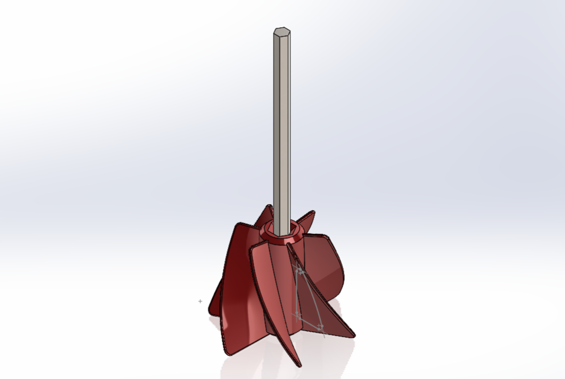
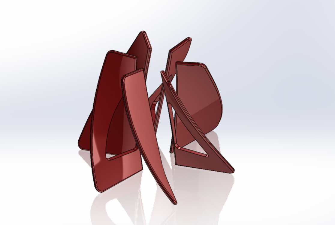
In this example, a paint mixer attachment needs a cutout applied, but to only three of the six fins. A revolved cut will accomplish what we need, but by default will pass through all six fins, with no control over which fins to ignore.
Manually Selecting Bodies in SOLIDWORKS
This part was designed from a single fin that was copied through a circular pattern. Rolling back before the bodies were merged is the first step because a key requirement of Feature Scope is that the targets must be separate solid bodies. In fact, you can think of Feature Scope as defining the scope of bodies to which the feature is applied.
So, the revolved cut will be applied again, but this time Feature Scope appears in the PropertyManager because a multibody part has been detected. The default selection is Selected Bodies, with Auto-select checked on. To control which bodies are targeted, Auto-select must be cleared, and the desired fins must be picked from the graphics area.
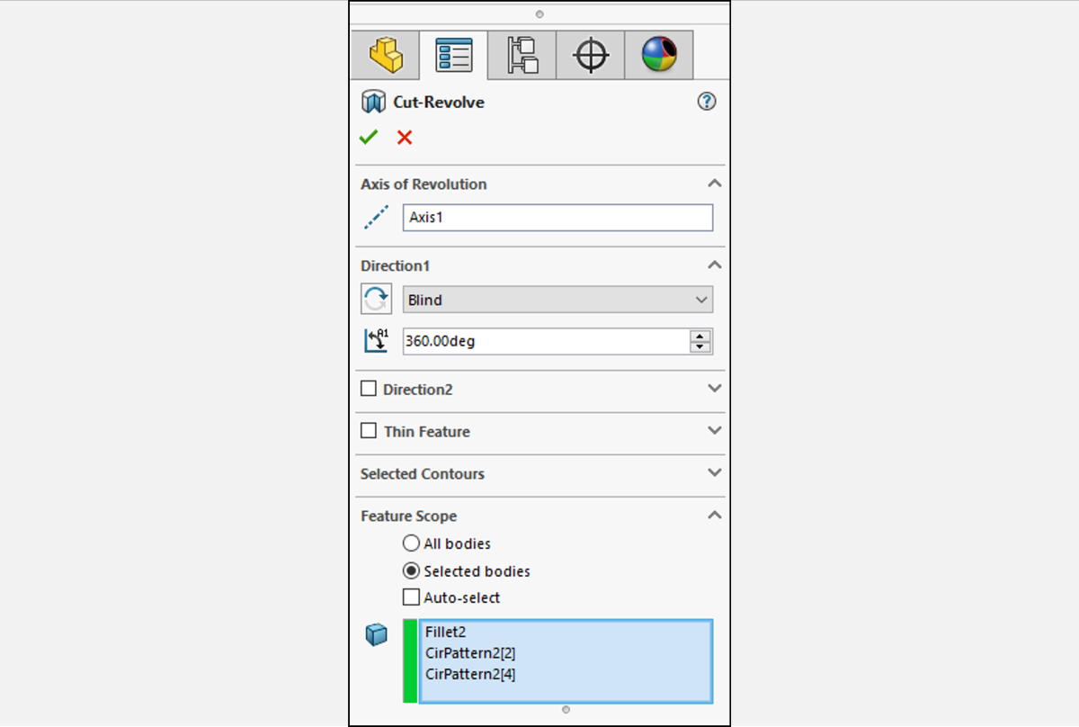
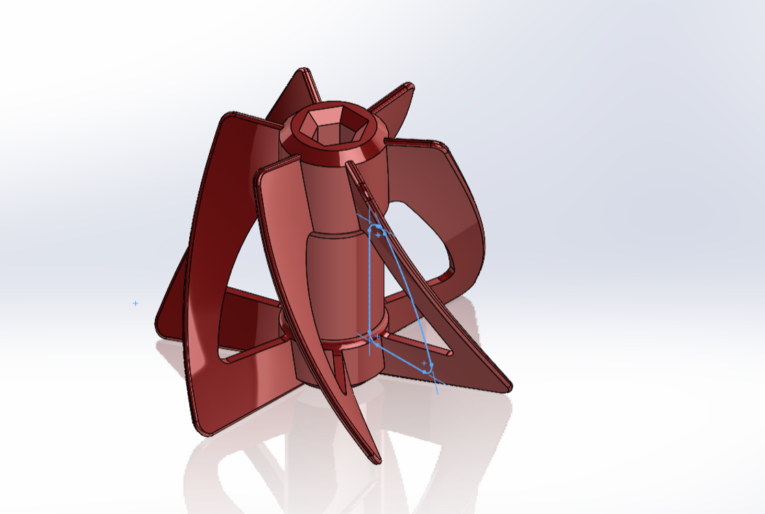
The selection box is populated with these choices and accepting the command results in only those 3 fins being cut – even though the other three fins were in that revolved path! Ignoring bodies is the key function of Feature Scope.
Auto-Select vs All Bodies in SOLIDWORKS
The other options within Feature Scope – All Bodies, and Selected Bodies with Auto-select checked – differ in how new bodies are affected when added to the part.
Auto-select will automatically select the bodies that intersect its path, similar to the default behavior. It also groups the bodies in the selection box automatically. This is significant because the use of the selection box is what causes it to be different from the All Bodies option – it’s applied to all current bodies. New bodies will not be affected by the feature.
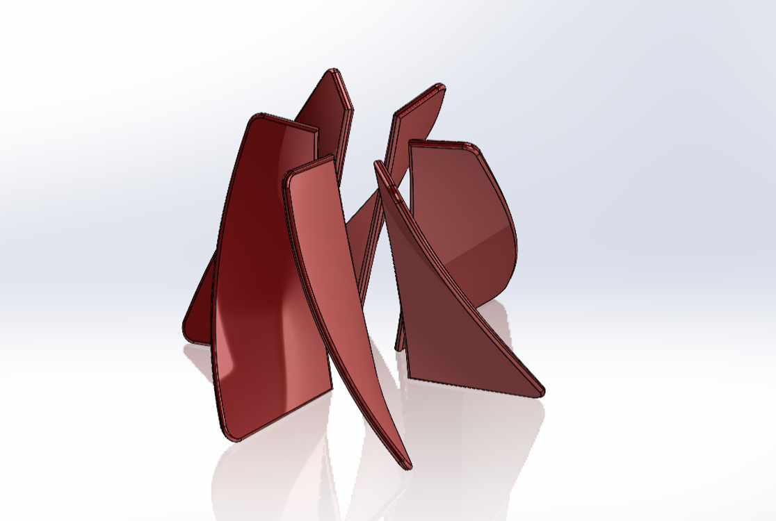
The image below shows the six Paint Mixer fins cut with Auto-select turned on, and then two fins added by editing the circular pattern.
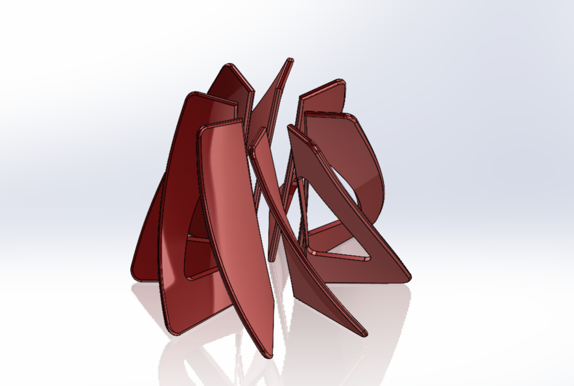
The All Bodies option targets all bodies that intersect its path, and checks for new bodies during each rebuild – new bodies will be affected by the feature. Note that this causes longer processing time.
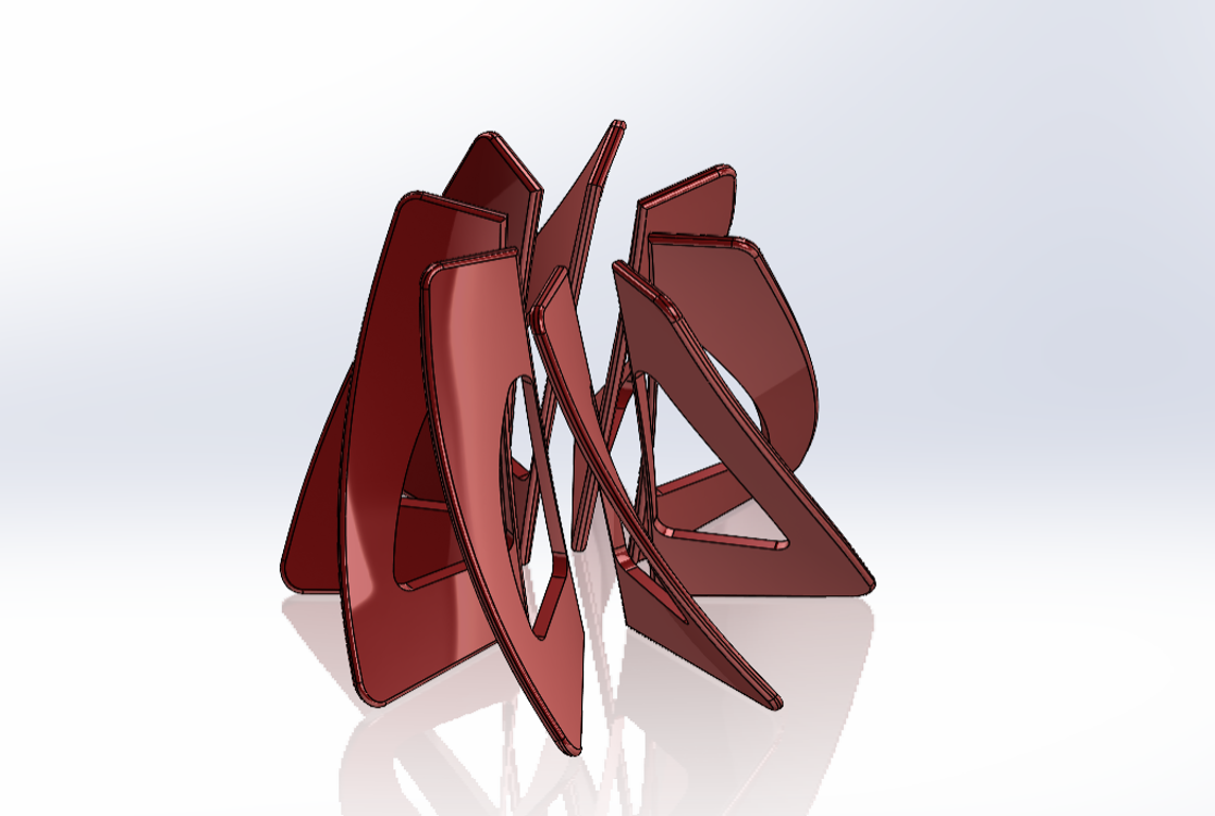
The next image shows the six Paint Mixer fins cut with All Bodies selected, and two fins added after by modifying the circular pattern.
Keep in mind that although this example showed a revolved cut, many features contain Feature Scope including material positive operations like Boss-Extrude.
Learn More with Advanced Part Modeling for SOLIDWORKS
We hope you found this tutorial useful, but if you need more information, you can learn even more about multibody part modeling in this SolidProfessor course which is included in your Hawk Ridge Systems Elite or Essentials subscription: Multibody Part Design.
Alternatively, you can also sharpen your skills with training from our highly qualified live instructors in this Advanced Part Modeling Course for SOLIDWORKS.
If you have other questions or needs for engineering services, please contact our team and visit us at hawkridgesys.com.