Most of us have undoubtedly used configurations in SOLIDWORKS. They are perfect for capturing multiple versions of our designs in a single part or assembly file. But have you ever utilized the power of Design Tables?
Design Tables harness the power of configurations and the flexibility of Microsoft Excel to give us high-level control over our parts and assemblies. We’ve introduced Design Tables in our previous blog post How to Utilize Design Tables in SOLIDWORKS and expanded on some best practices in our blog post 7 Steps to Creating Effective Design Tables in SOLIDWORKS. In this article, we will delve even further into how you can leverage Design Tables to get the most out of your designs. So, get ready and read on for a deep dive into Design Tables and how to use them!
Inserting a Design Table
We first discussed how to insert a Design Table into our parts and assemblies in our previous blog post (be sure to check that post out as well). We also went over Design Table creation and use in our other blog posts and videos. As a refresher, you can insert a Design Table from the drop-down menu: Insert > Tables > Excel Design Table.
There are several options that affect the behavior of Design Tables and how they apply to designs. Unfortunately, these options are not fully understood by many SOLIDWORKS users. To that end, we will see exactly what each of the options in the Design Table PropertyManager are used for.
Design Table PropertyManager Parameters
Note: These parameters (other than the “Source”) can also be modified after the Design Table has been created.
Source
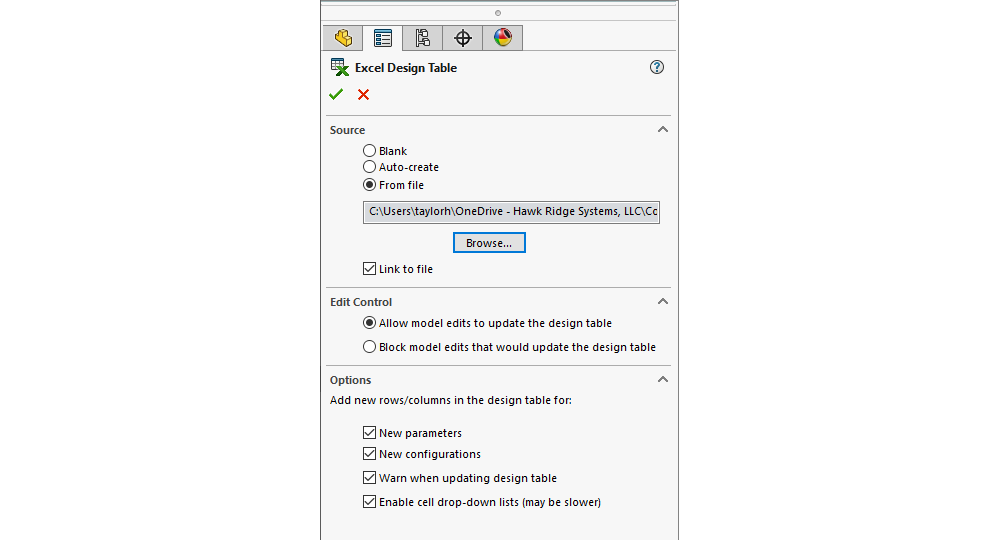
You have three options to choose from for the source when creating a Design Table:
- Blank – Inserts an empty Design Table that you populate manually.
- Auto-create – Inserts an automatically-generated Design Table containing each of the configured parameters and their associated values from the part or assembly.
- From file – Inserts a Design Table from an external Excel file.
- Link to file – When using an external Excel file, we can choose to link our Design Table to that file or to leave it unlinked.
Typically, selecting “Auto-create” works best when starting out, especially if we are new to Design Tables. This option automatically generates a Design Table with the correct format and includes any parameters you’ve already configured, making it easy to edit and customize the table to fit your needs. After the Design Table is generated, we can save it externally and link it to our model for easy design management directly from Excel.
Edit Control
The edit control options let us control how changes to our model are propagated to the Design Table:
- Allow model edits to update the design table – Allows changes at the model level to propagate to the Design Table.
- Block model edits that would update the design table – Prevents model changes from affecting the Design Table.
Your selection here depends on how you want to control the designs—do you want the Design Table to be the controlling document? Or do you still want to make edits in SOLIDWORKS that will propagate into the Design Table? The correct option depends on your own workflow.
Design Table Options
These remaining options allow us to determine how the Design Table updates with new columns and/or rows when changes are made.
- New parameters – Adds a new column to the Design Table if a new parameter is added to the model.
- New configurations – Adds a new row to the Design Table if a new configuration is added to the model.
- Warn when updating design table – Displays a warning if changes to model parameters will update the design table.
- Enable cell drop-down lists – Adds drop-down lists to Design Table cells for relevant parameters.
Formatting and Customizing Design Tables
If you use the “Auto-create” option (which is recommended when first starting a Design Table), the table is generated with the correct format and includes any parameters that you have already configured in SOLIDWORKS. You can use this pre-populated table to add or remove parameters and customize the design table as needed. Let’s discuss the distinct areas of the design table and what each is used for.
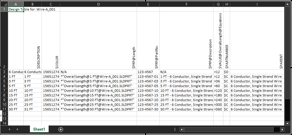
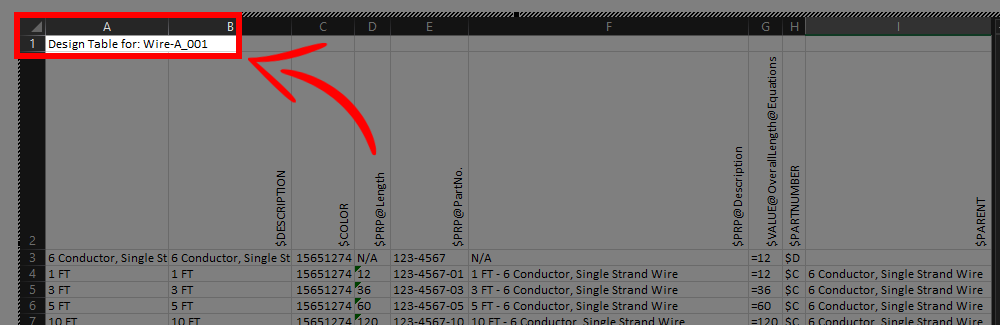
Design Table Title
The Design Table title lives in cell A1 of the spreadsheet. The value of this cell has no effect on our part or assembly in SOLIDWORKS. By default, the value is “Design Table for: *PART NAME*”, but it can be changed to whatever text value you want to be descriptive of what the table is for. In most cases, the default name is acceptable. We recommend changing the title value in cases where the Design Table may be used for multiple parts or assemblies. In this case, a descriptive title will help whoever is using it understand what the table should be used for (for an example see the “Design Table Import, Export, and Linking to an External File” section below).
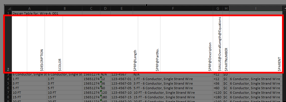
Design Table Header
The second row of the Design Table (Row 2) is the header of our table. The header is where you define the parameters that you wish to configure and control. If there is any aspect of your design that you want to control via the Design Table, all you need to do is populate this header row with the applicable parameter name. A description of common parameters is given in the next section below.
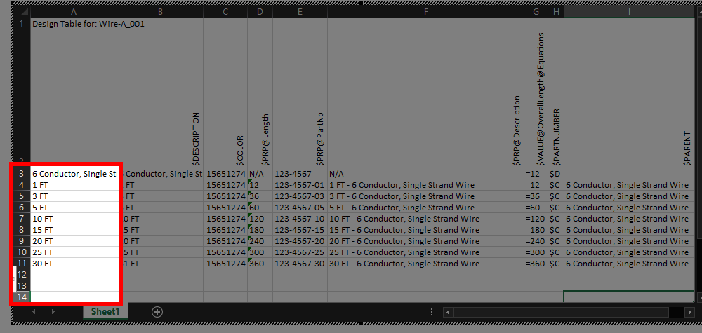
Design Table Configurations
In column A of the remaining rows (A3 and below) in the Design Table header, you can define your configurations by entering your desired configuration names. Each row of column A that you populate with a configuration name in column A will generate a new configuration. From here, you can add or remove configurations on your part or assembly as necessary.
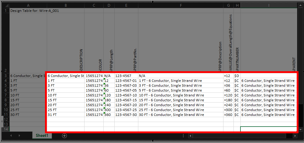
Design Table Parameter Values
In the remaining columns of row 3 and onward, you can enter the desired values for each of the parameters you defined in the Design Table header, per configuration. Each parameter has a specific type of data that it can accept (e.g., text, number, SOLIDWORKS data) as well as default behavior if no value is entered. See the next section below for common parameters and their usage and the end of this blog post for a full list.
Design Table Parameters
Virtually all configurable parameters in a part or assembly can be controlled via a Design Table. This includes parameters such as suppression states, Global Variable values, materials for individual bodies, and even tolerances for specific dimensions. By using Design Tables, you can control and modify each of these parameters, and more, all from within a single spreadsheet.
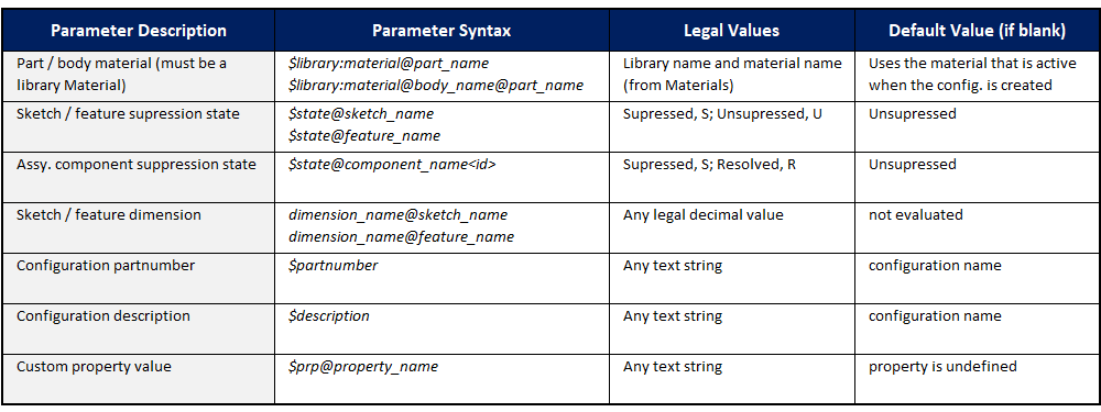
Below is a list of some of the commonly used parameters and examples of their usage (a more complete list of these parameters is given at the end of this blog):
Design Table Import, Export, and Linking to an External File
It can be useful to save your Design Tables as external files linked to your models. This way you can edit the parameters of parts and assemblies in Excel. As a result, you can review and update designs even if you are working on a machine without SOLIDWORKS installed. This is beneficial when working with complex parts or assemblies.
This is particularly true for designs with tons of configurations that would otherwise require significant rebuild time as each change is made. With a Design table, instead of making changes configuration by configuration, you can make all the changes you need, to all configurations, all at once.
Saving your Design Tables as external files also allows you to use them akin to configuration “templates”. If you have configurable parameters that are similar between multiple designs, you can create and export the Design Table once and then import it into any other files that would use those same parameters.
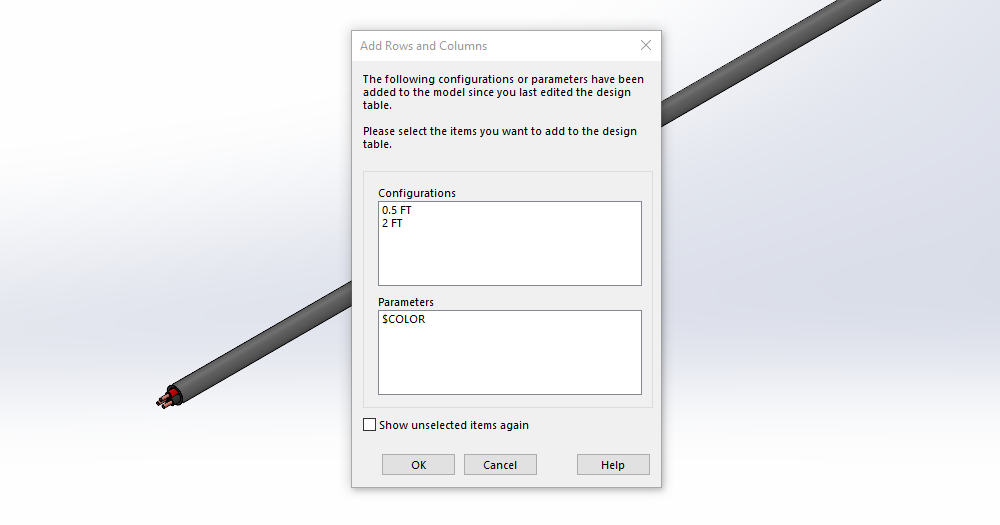
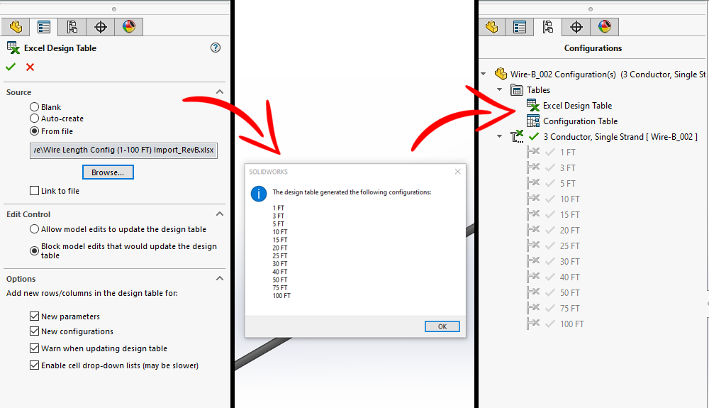
External Design Tables are also a productive way to create many configurations all at once. Instead of creating configurations manually in SOLIDWORKS, you can generate any number of configurations, with all the correct parameters defined, simply by importing an existing Design Table.
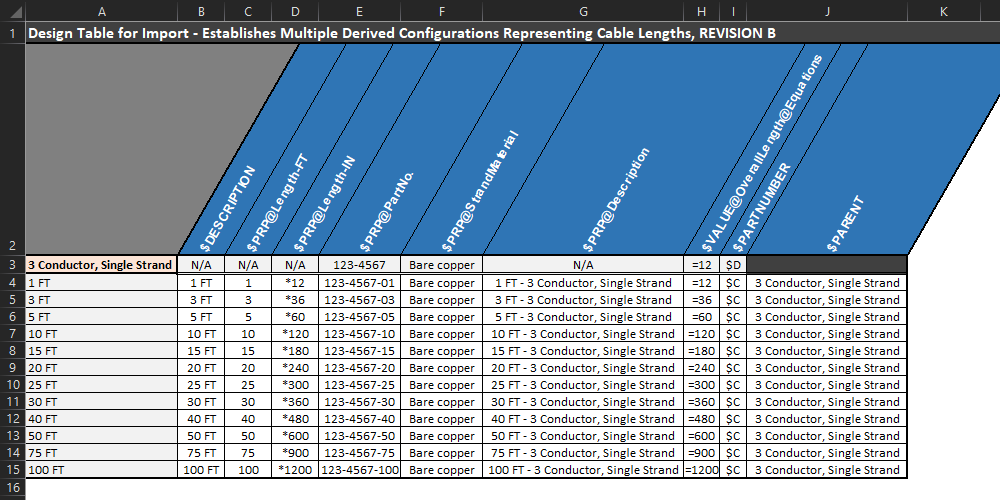
In the next image, we use the example of creating derived configurations to represent different lengths of a wire. We create twelve configurations, all at once, with all the correct per-configuration parameters, simply by importing our Design Table.
Using externally linked files for your Design Tables also allows you to customize them very easily in Excel. Excel equations and formatting can be used in Design Tables so long as the correct data is in the correct location for the overall layout of the table. This can often help organize and manage Design Tables while at the same time making them more readable. I personally prefer using externally linked Design Tables so that I can modify my designs through a regular Excel window instead of the embedded SOLIDWORKS interface (it also means that I don’t need SOLIDWORKS to be open to make design changes!).
List of Configuration Parameters for Use in Design Tables
Below is a list of the configurable parameters that you can control via Design Tables. As you can see from this list, there are a vast number of ways to control designs by utilizing Design Tables. Be sure you understand what each parameter does before using it to manage designs—we recommend testing often.
You want to ensure that you have a good understanding of these parameters to ensure that your models behave the way we expect.
- Base Parts in Configurations
- Color Parameter in Configurations
- Comment in Configurations
- Component Configuration
- Component Part Number in Configurations
- Component Suppression State in Configurations
- Cosmetic Threads in Configurations
- Custom Properties in Configurations
- Derived Configurations in Design Tables
- Description in Configurations
- Dimensions in Configurations
- Display States in Configurations
- End Conditions in Configurations
- Expand in BOM in Configurations
- External Sketch Relations in Configurations
- Feature Suppression State in Configurations
- Shortcuts for Suppressing Items in Design Tables
- Fixed or Floating Position in Configurations
- Global Variables in Configurations
- Hole Sizes in Configurations
- Lighting in Configurations
- Mass Properties in Configurations
- Materials in Configurations
- Scale Features in Configurations
- Sketch Dimensions in Configurations
- Sketch Planes in Configurations
- Sketch Relations in Configurations
- Sketch Suppression State in Configurations
- Split Parts in Configurations
- Tolerances in Configurations
- User Notes in Design Tables
More Resources for Uusing Design Tables
Hopefully, this blog post gave you additional insight on how to make use of Design Tables to manage your designs. As you’ve seen thus far, Design Tables can be powerful design tools to help you manage your designs and models more efficiently. Be sure to check out our other content related to Designs Tables as well:
- 7 Steps to Creating Effective Design Tables in SOLIDWORKS (blog)
- How to Utilize Design Tables in SOLIDWORKS (blog)
- Design Tables (blog)
- Configuring Materials for Different Configurations (YouTube video)
As always, if you have any questions, contact us at Hawk Ridge Systems. We can also discuss how the suite of SOLIDWORKS software can help improve your workflows and designs.