
Working with SOLIDWORKS and Excel in the same space is very common. But what if you could use Excel tables inside SOLIDWORKS to control configurations? Or to suppress features, change dimensions and materials? Then you wouldn’t have to worry about affecting other configurations. Now, there are different ways for us to create the design tables. In this blog, we will create design tables for the net magnet part using “auto-create” and inserting a blank table.
Creating a Table
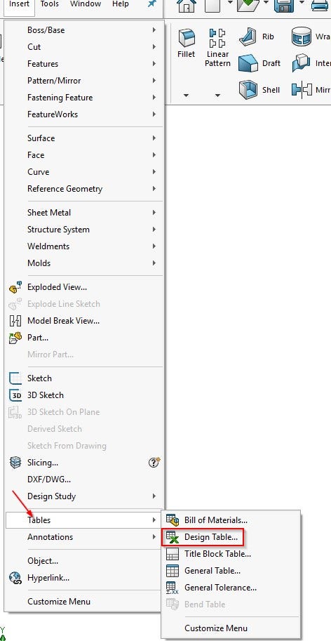
To make your table, first go to Insert in the drop-down menus and click on Tables. Once there, click on Design Tables.
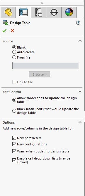
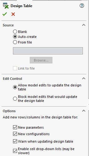
Inside the Property Manager, there are different options for creating your table. For this first table, select inserting a Blank table. We will also leave “Allow model edits to update the design table” checked inside the Edit Control portion. That way, if any changes are done they will be reflected in the Design Table. In the Options you can add rows and columns for the design table to create a new parameter, new configurations, warn when updating the design table and enable cell drop down. We will leave all of these checked on.
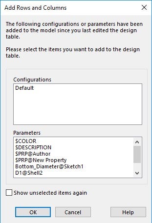
Now, we click OK and an Excel table appears. Another box appears called the Add Rows and Columns that contains all the current configurations and parameters that can be added. We won’t be adding any parameters so you can click OK.
Adding Configurations
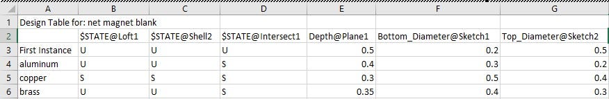
Now that the table is active, we see that there is only one configuration called the initial. In the rows, you can type in other configurations. The net magnet part will have three other configurations so we will add Aluminum, Copper and Brass. The table acts like the configure feature table where you double click on a dimension or feature and it’s added to the Design Table. The top and bottom diameter dimensions of the net magnet are added to the Design Tables. The depth will also be added to the table as well. The Features that the table will be suppressed or unsuppressed are the Loft, Intersect and Shell. When it comes to features, you can either type suppressed or unsuppressed.
A shorter way to do this is just to either type “U” for unsuppressed or “S” to suppress the feature. After selecting the dimensions we want and features to be suppressed, the table is ready to be modified. Now, to have the table be applied to the model we can click on the green check mark on the top right corner or just click in the graphics area and have it applied.
Using the Auto-Create Feature
We are now going to recreate the same table but this time we will be using Auto-Create. The same parameters that were used in the previous example will be used. One thing we have to take of note is that a part can only have one Design Table. So, this Design Table will be created from a different part.
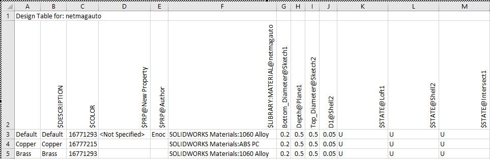
Now after selecting Auto-Create and clicking OK, a dimension toolbox appears if you only have a default configuration, that lets you select the dimensions you want to control inside the Design Table. Since the net magnet part already has the Copper and Brass configuration the table auto-populates dimensions and material inside the table without us having to double click on them. Notice that it also has added new property and color columns automatically.
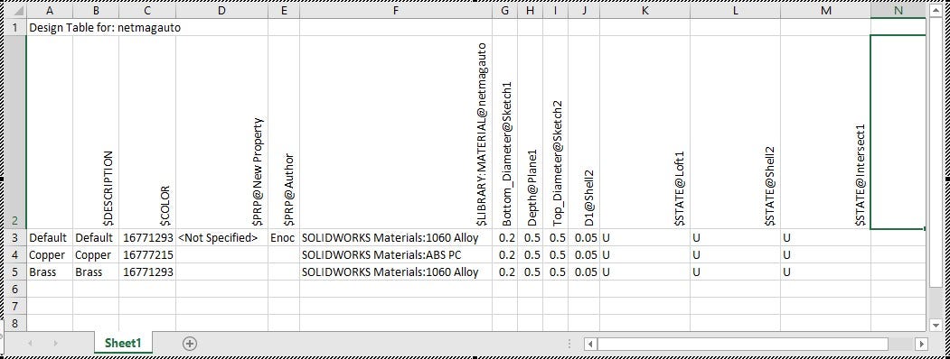
We are still able to add features just like before. So, we will double click on the Loft, Shell and Intersect. Those features are now able to be suppressed and unsuppressed in the table.
With tables being so easy to create, it’s a shame to not use them. We have seen how easy it is to create a blank table and fill it in with the right parameters we want to control. We’ve also seen how SOLIDWORKS can automate the creation of a Design Table with existing configurations. If you have any tips or tricks on the Design Table, let us know in the comments!
For more information on SOLIDWORKS or if you have any questions, contact us at Hawk Ridge Systems today. Thanks for reading!


