
Creating Accurate Volume Measurement in Five Easy Steps
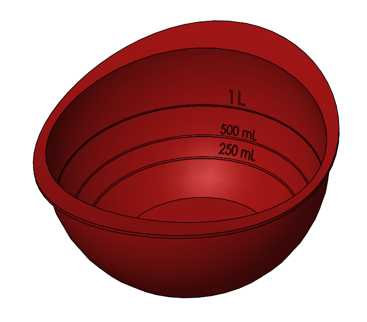
In this blog, I am going to show you how to determine where a specific volume of fluid will lie inside a container and then a modeling technique to create a level marker. I am going to use the intersect command to create a fluid body, a sensor to record the volume of that fluid body, and then a design study to get the volume exactly where I want it to be. The results will look like Figure 1 and we’ll use the following steps:
- Create a plane for the fluid level
- Create a fluid body
- Create a sensor monitoring the fluid volume
- Create a design study to optimize the volume of the fluid
- Create the volume marker
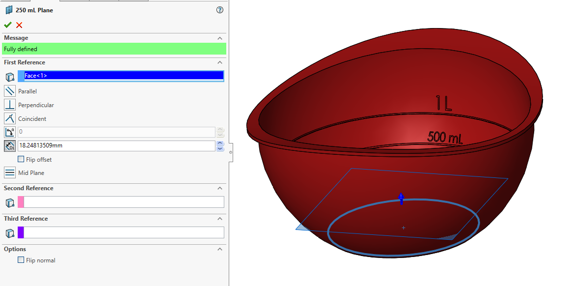
Step 1: Create a plane for the fluid level.
The first step is to create a plane to represent the fluid level. The height at this moment is not important as long as it intersects the container. Figure 2 is the plane created for the 250 mL level marker. The plane is parallel to the bottom of the bowl and has an offset causing the plane to intersect the bowl.
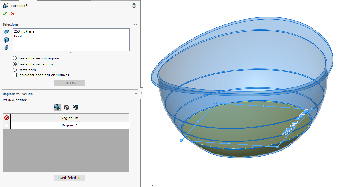
Step 2: Create a fluid body.
Using the intersect command a body representing the fluid volume can be created from the region of empty space between the bowl and the plane. Figure 3 is the PropertyManager of the Intersect command used to create a solid body representing the fluid volume. I renamed this body to “250mL Fluid” for ease of use.
Step 3: Create a sensor monitoring the fluid volume.
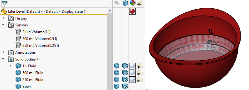
The next step is to create a sensor monitoring the fluid volume of the newly created solid body. Figure 4 is the PropertyManager of the sensor tool. The sensor type is set to Mass Properties and the Property it is sensing is the Volume. The “250mL Fluid” solid body is selected for the sensor.
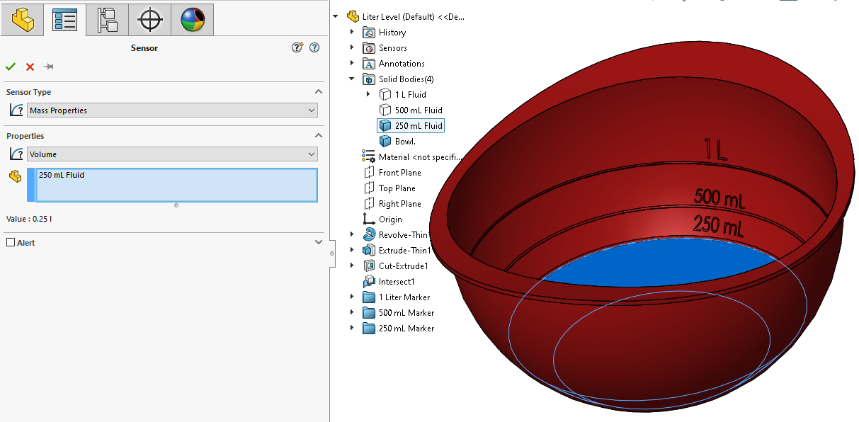
The sensor will allow me to constantly monitor the volume of the selected body from the feature manager design tree as seen in Figure 5 and use it as a goal or constraint in a design study.
Step 4: Create a design study to optimize the volume of the fluid.
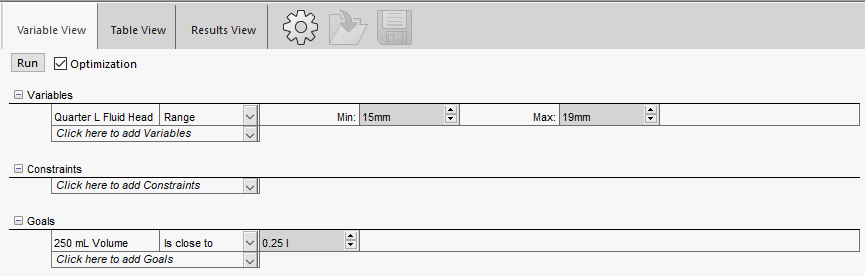
Design studies in SOLIDWORKS allow the manipulation of a variable and observe or optimize a sensor reading. In this example, the height of the fluid level or the dimensional offset for the plane will be manipulated until the volume sensor reads exactly 250mL. If you have a license of SIMULATION PROFESSIONAL, you have an Optimization button inside of the design study which allows the input of a range for the manipulated variable and SOLIDWORKS will find the optimal value for a goal. Figure 6 is the design study set up using Optimization where the Fluid Head Plane is ranged between 15mm and 19mm with the goal of getting the fluid volume as close to 0.25L as possible.
After hitting run, SOLIDWORKS will change the manipulated variable to the min, max, and average values to get an understanding of how the sensor responds to the manipulated variable. Then it predicts an optimal value and shows the results view in Figure 7.
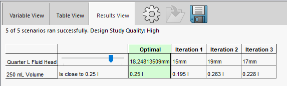
This will set the plane at the perfect level for the desired volume, and I can then begin to sketch on the plane. Conversely, I could also sketch on the top face of the solid body representing the fluid volume as the two are coincident.
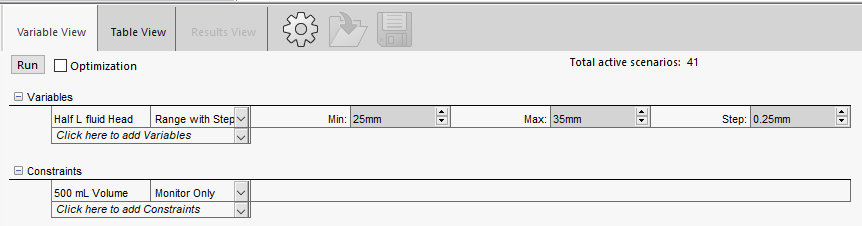
If you do not have a SIMULATION PROFESSIONAL license, you can still run a design study. It is just a more manual process. Without the optimization setting, the manipulated variable can vary through a range, but you must supply a step size. For the 500mL marker, the range was set from 25mm-35mm and a step size of 0.25mm giving a total of 41 scenarios as seen in Figure 8. The volume sensor is set as a constraint and the value will be monitored.
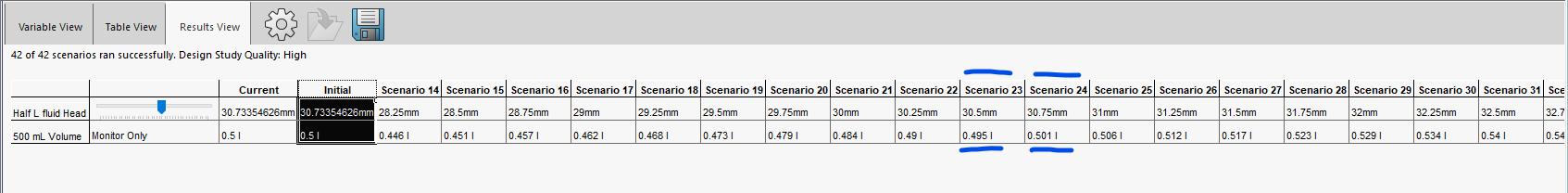
Since there are 41 scenarios, it will take ten times as long as the optimization study, but luckily the rebuild time is under a second, so the full design study only took about 15s to run. From the results in Figure 9, we can see half a liter of volume is achieved between 30.5mm and 30.75mm of fluid head.
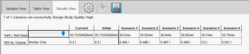
This is not an exact value, so the process needs to be iterated until the desired precision is achieved. Doing one more Design Study between 30.5mm and 30.75mm with a step size of 0.05mm yielded a volume of 0.5L when the fluid head was at 30.7mm, as seen in Figure 10.
Step 5. Create the volume marker.
There are a variety of ways to make this marker. The method you choose depends on your manufacturing process.
My bowl is going to be molded silicone, so the product will be flexible enough to peel around the undercut created by the marker.
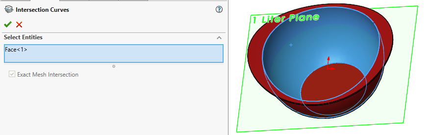
Since there is a plane at the height of the fluid, I will create a sketch on the plane and use an intersection curve to create a sketch entity where the plate intersects the inside face of the bowl. Figure 11 is the PropertyManager of the intersection curve with the selections shown beside in the graphics area.
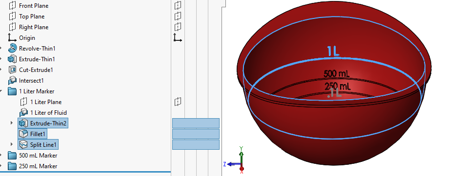
Now that the sketch is complete, I can create a thin extrusion for the marker. Remember to start at the bottom because the new marker will affect the volume for lines above it. To get some lettering, you can use the wrap command to inscribe or emboss some lettering onto the curve or use the split face command to change the topology. Figure 12 shows the FeatureManager Design Tree and the approach I used to mark the bowl after finding the appropriate locations.
As you can see, SOLIDWORKS is a very powerful modeling tool that you can use to accurately find the volume of a container and create markings for it to communicate that with your consumer.
For more information, check out our YouTube channel or contact us at Hawk Ridge Systems today.


