When programming a part in CAMWorks, I always set up my machine and choose the stock size that I will use first. To get started programming a 3 Axis part, I’ll discuss the Multi Surface Feature.
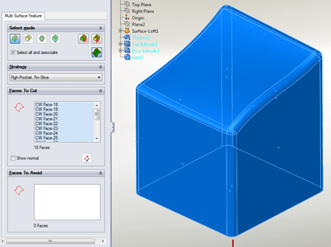
Right Click on Stock Manager in the CW Tab and select Insert Mill Part Setup or use an existing setup if you have one. Choose the appropriate plane or face to reference your Z-axis. You can always choose to toggle the direction of your setup to change the spindle direction to be correct. Right click on the Mill Part Setup that has been created in the CW Tab and select Insert Multi Surface Feature.

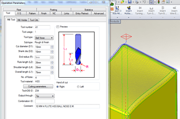
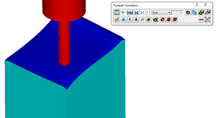
Check the Select all and associate check box to select all of the faces of the part or manually pick each one in the graphics area. Generate Operation Plan will generate the operations in the Operation tree based on the strategy defined in the feature. Once the operations are generated you can modify tool sizes, pattern types etc. by double clicking an operation and then use Generate Toolpath and Simulate Toolpath to analyze the results.


