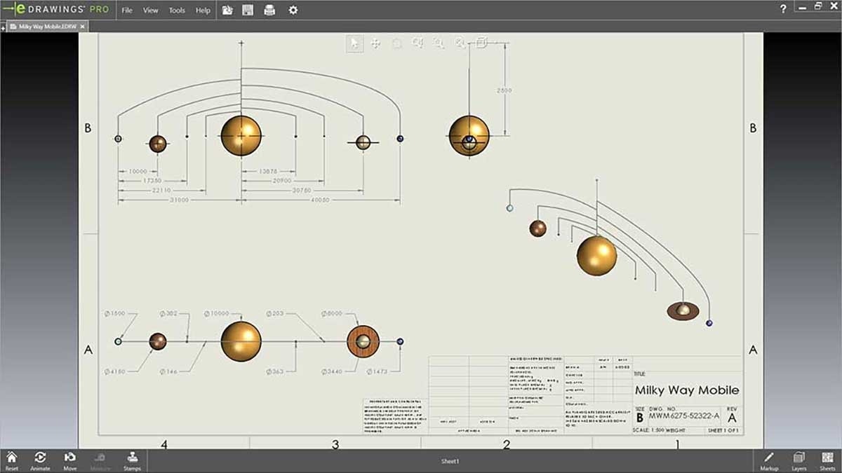
Making engineering drawings look clean while still including all relevant design and manufacturing considerations can be a huge undertaking at times. Technical drawings should be something you are proud to hand to your manufacturing team or customer while serving the functional purpose of conveying all necessary specifications. There is also a fine balance between providing a high level of detail and displaying a clean, visually palatable layout that doesn’t leave the viewer cursing the heavens above.
Bearing this in mind, SOLIDWORKS provides an array of tools to align drawing entities and make your sheets look out of this world. This article looks to showcase these capabilities and walk through some specific alignment features, all while attempting to increase awareness of how you want to organize your drawing layout. The three main types of drawing components to spatially control covered here are views, annotations and title block notes.
Drawing Views
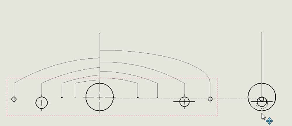
In most cases, the drawing entities that occupy the most significant amount of space are the various views that show the model from multiple perspectives. The standard three-view drawing usually has one anchor/parent view from which the other two orthogonal/projected views are derived along with an isometric view. The parent view and two projected views are automatically aligned in SOLIDWORKS to be constrained to their connected direction, shown below when dragging the right projected view horizontally from the front parent view.
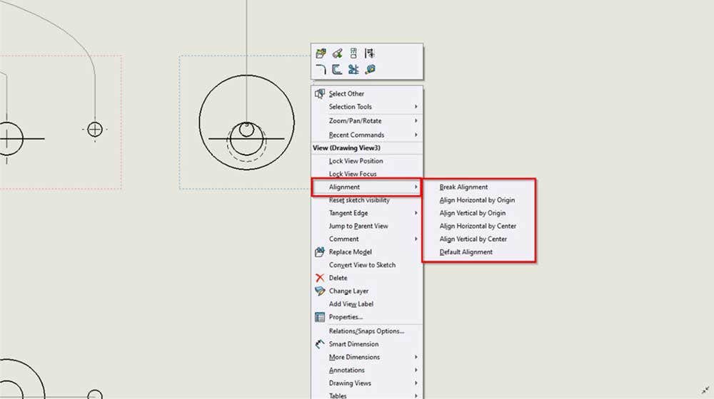
To break that alignment link, there is a simple right-click ripcord to pull once hovering over the projected view, as shown below, or when view is selected in the top dropdown menu under Tools > Align Drawing View. Once broken, the weightlessly free-floating projected view can be moved in any direction. There are five additional alignment options given; Align Horizontal by Origin, Align Vertical by Origin, Align Horizontal by Center, Align Vertical by Center, and Default Alignment (aka restore original alignment). If aligning a view horizontally or vertically, it will prompt you to select which view you are using as the reference to connect it with. These alignment capabilities are also available for Auxiliary, Section, and Removed Section Views.
Annotations
If views are the planets in the solar system that is our drawing sheet, annotations are the stars that illuminate the void of model space with essential specs. There are a vast range of ways to line up these dimensions and notes in an organized arrangement that is clean and concise. Let’s walk through some key methods to enhance the constellations of annotations.
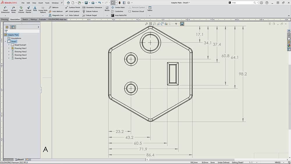
The Autodimension tool (Annotation Tab > Smart Dimension > Autodimension tab) automatically creates dimensions organized in either a Baseline, Chain, or Ordinate scheme (see example of each below) in both the horizontal and vertical direction for whatever origin is specified. The benefit to this method is that it quickly populates consistent spacing relations between dimensions and the associated witness/leader. There might be some final manual adjustments warranted depending on the number of dimensions and input settings.
Baseline
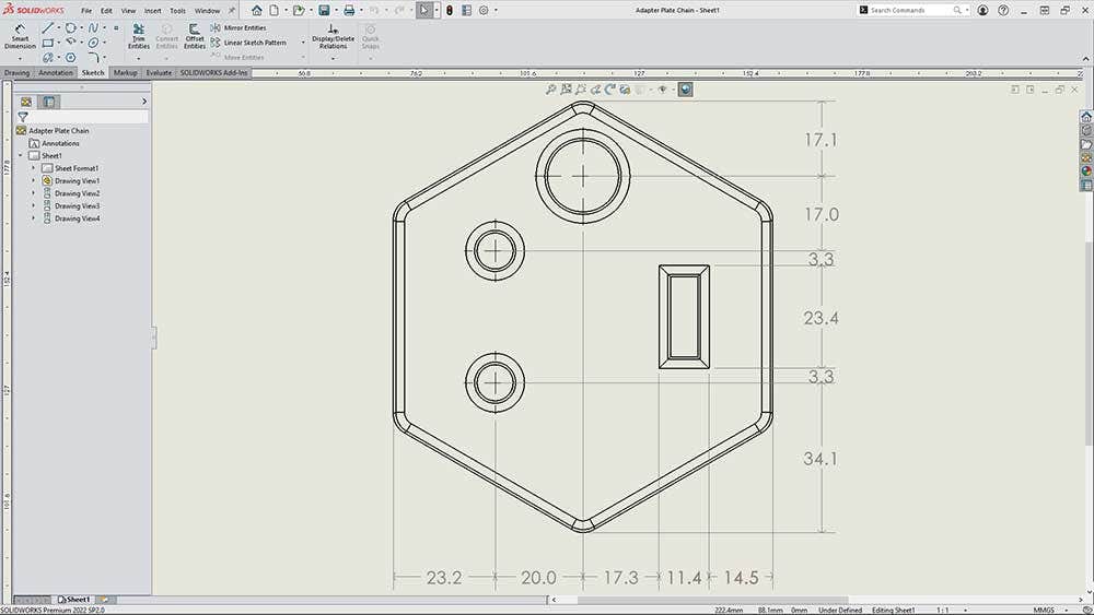
Chain
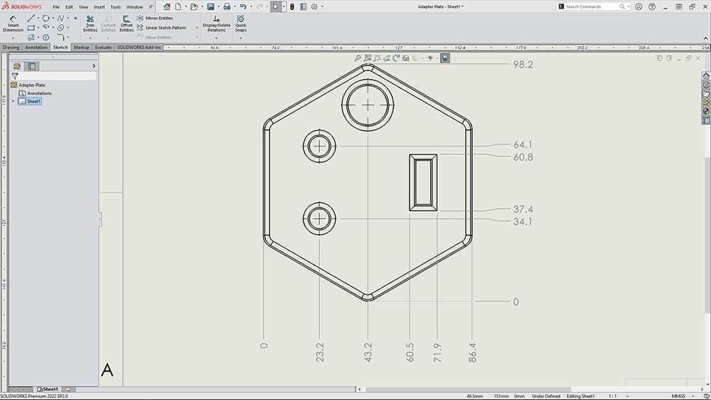
Ordinate
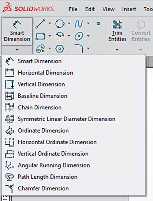
Additionally, the Smart Dimension dropdown menu has more specialized dimensioning styles (see below) to assist in neatly orienting design callouts to look exactly how you want them.
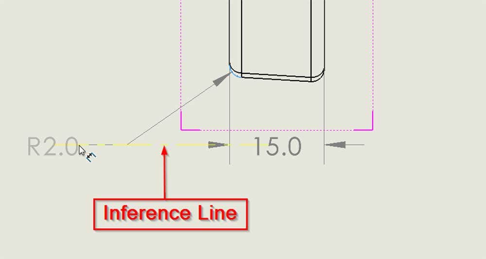
If adding dimensions by hand or importing them from the original part or assembly file, there is always the ability to align dimensions to each other via inference lines. In the screenshot below, dragging the R2.0 dimension horizontal to the existing 15.0 dimension snaps directly to dashed yellow inference line that appears. It should be mentioned that the dimensions being aligned must be in the same drawing view.
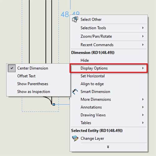
Right clicking on an existing dimension brings up a few useful positioning and visual settings under Display Options, as shown below.
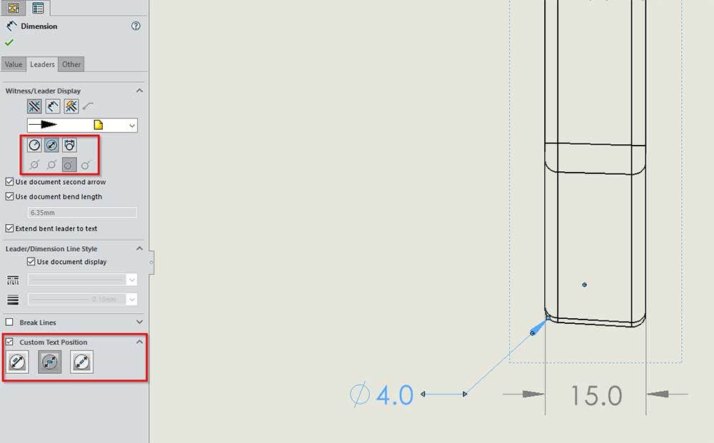
Finally, the positioning of the dimension with respect to the leader can be customized to a stellar level of detail and relevancy depending on what type of dimension it is. Once the dimension is selected, the Property Manager on the left side of the screen opens and under the Leader tab you can see below the radius/diameter display styles as well as Custom Text Position options.
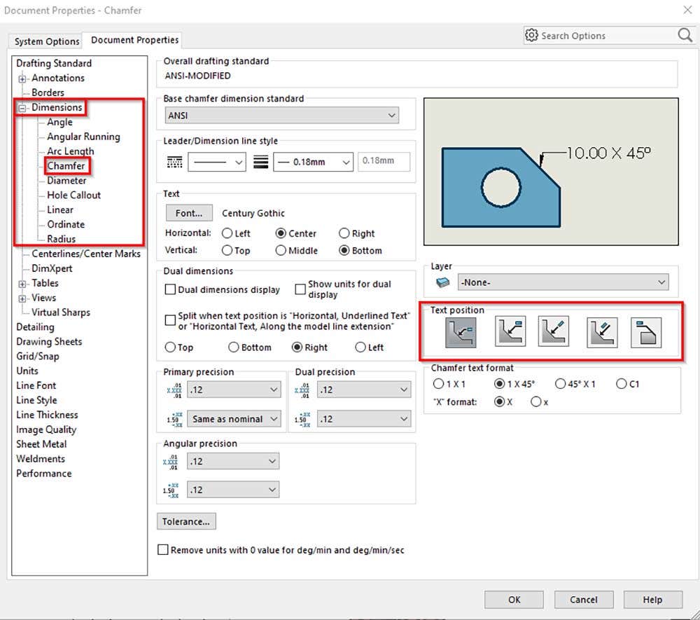
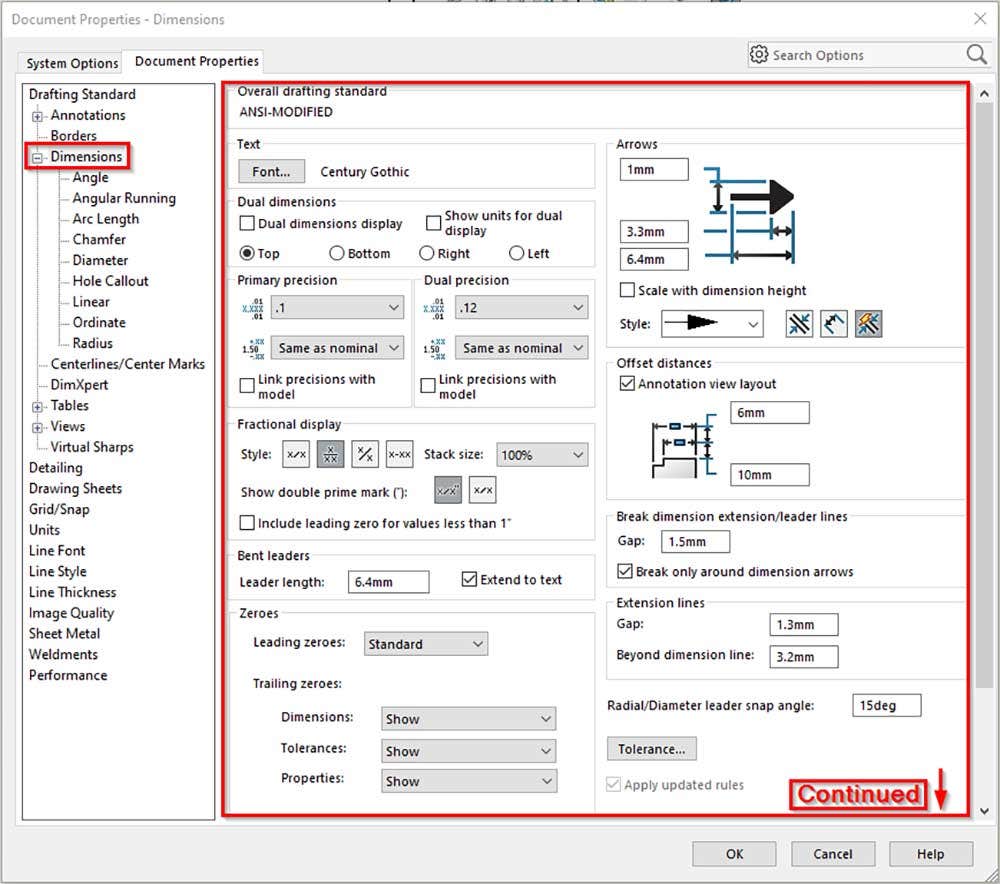
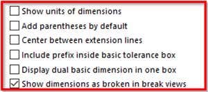
These options can also be accessed from Options > Document Properties > Dimensions as shown in the screenshots below. Note that editing any settings in Document Properties will apply to all dimensions in your drawing going forward, not retroactively. The first image depicts one type of dimension and all the related components of its positioning. The second and third images are the options for top level dimensions, allowing for the tailoring of universal settings for spacing, tolerancing and style.
Title Block
The last astral alignment element of drawings covered here is the title block, anchoring the sheet space station like a sturdy tether. Ideally, all title block information would automatically update from a standardized drawing template (watch our videos, “Drawing Templates from Scratch in SOLIDWORKS: Part One” and “Drawing Templates from Scratch in SOLIDWORKS Part Two” for examples. In this process, proper alignment tools will add order, consistency, and cosmic prestige to every drawing you create. To begin editing the title block, either right click a sheet/the graphics area or alternatively, select Edit Sheet Format in the Sheet Format Command Manager tab.
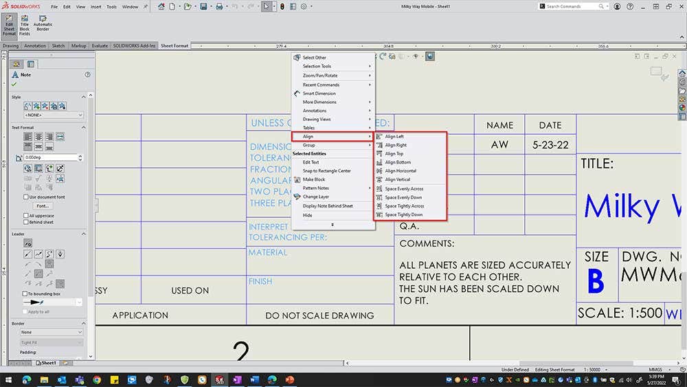
Organizing title block headers into a clean arrangement can be as simple as group selecting (hold ctrl while clicking) all the individual notes to be lined up and right clicking to select the Align fly out, as seen below. Beyond the usual left, right, top, and bottom alignment options, there are horizontal and vertical selections in addition to automatic spacing tools for your convenience.
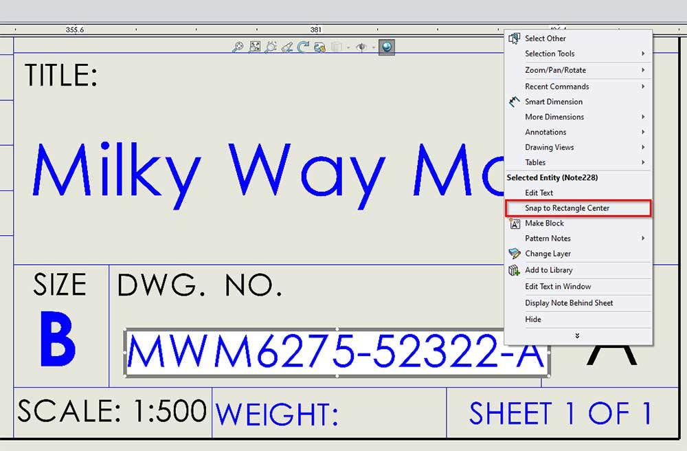
Alternatively, to center your property/note within its correct title block orbital, there is another way to propel it instantly. First, right click the text box, in the example below it is the MWM6275-52322-A drawing number, then choose the Snap to Rectangle Center option.
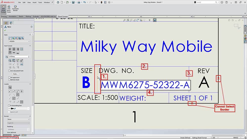
Now as seen below, the left side of the status bar (bottom left corner of image) is prompting the selection of 4 sides of a rectangle to contain the text. The four lines that enclose the drawing number are then selected, as tagged with the red numbers one through four added to the screenshot. The order in which these lines are selected does not matter. Once the fourth line is selected, the text performs a light-year jump to the center of the rectangle like a blackhole pulling celestial debris into its nebulous core. Note that the actual sheet border cannot be selected for a rectangle side so you may have to sketch a line manually before selection to properly utilize this alignment tool.
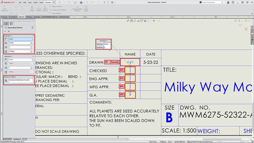
Finally, to pattern a title block note, right click the “seed” or original text to be duplicated (in the case below it’s the AW initials note) then choose the Pattern Notes flyout to select either the Linear or Circular Note Pattern. As previewed in the icons or if you are familiar with the function to pattern sketch or feature entities in part files, the linear pattern will prompt the input of either one/two linear directions or one circular center point as a reference in which to then pattern your note whatever distance for however many instances you select. The example below will result in five total instances, including the seed, spaced 4.8mm apart between note centers along the X-axis (vertical on sheet) direction. To change the direction, either drag the point of the direction arrow in the graphics area or adjust the numerical angle input (270deg) on the Property Manager window.
There are infinite ways to utilize SOLIDWORKS’ organizational alignment instruments to elevate your drawings. For more information on SOLIDWORKS or to ask our experts any questions you may have, contact us at Hawk Ridge Systems today. Thanks for reading!


