In the last part of the blog series, we’ll explore how we can import an
assembly created natively with Siemens Solid Edge then we can break the link
to the original 3rd party CAD file and utilize Feature Recognition, without
having to wait for the vendors to fix the geometry on their end. We’ll proceed
with opening a Solid Edge motor drive assembly this time by doing an ‘Insert
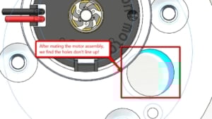
Components’ into our existing assembly. After adding some coincident and
concentric mates, we’ll find that the holes don’t line up!
 3D Interconnect lets an imported Solid Edge assembly be edited directly, without waiting on the vendor to fix it. 3D Interconnect lets an imported Solid Edge assembly be edited directly, without waiting on the vendor to fix it. |
What would you do in this case? Wait for the vendor to send you an updated
Solid Edge assembly? That could possibly take days, if not weeks. Another
option is to make the change ourselves using our direct editing tools! To do,
we’ll right click on the assembly, and select ‘Break link’.
 Right-clicking the imported assembly and selecting Break Link enables direct editing of its geometry. Right-clicking the imported assembly and selecting Break Link enables direct editing of its geometry. |
We’ll be prompted to verify if we do want to break the link, as it can’t be
undone. Once we confirm with a ‘Yes’, this will make the ‘Drive Motor
Assembly’ a virtual assembly, indicated by the brackets. From this point, we
can choose to either keep it Virtual (saved internally inside the assembly) or
save it out to an External file with a simple right-click on the Virtual
assembly.
 Confirming the break makes the assembly virtual, marked by brackets, allowing it to be edited in SOLIDWORKS. Confirming the break makes the assembly virtual, marked by brackets, allowing it to be edited in SOLIDWORKS. |
Afterward, we’ll want to focus in on the ‘Motor Plate Adapter’ because that’s
the hole we want to change. So we’ll ‘Break the link’ to the ‘Motor Plate
Adapter’ which creates virtual parts in the assembly, as well. If we take a
look at the FeatureManager, it will resemble similar to what we were used to
before 3D Interconnect – seeing the components come in as imported
body/bodies.


From this point on, we can do some direct editing, or Feature Recognition
either Automatically or Manually. To just do Feature Recognition on the
clearance hole, we can right-click the inside surface and click ‘Edit
Feature’. It’ll recognize the hole as an M7 clearance hole. This will provide
us with 2 sketches – 1 sketch for the cross-section and another sketch for the
position of the hole.


Since we want to make sure the ‘Motor Plate Adapter’ hole lines up with our
existing SOLIDWORKS assembly, we’ll pop back over to the assembly edit the
part in the context of the assembly. We’ll edit the position sketch, hide the
‘Motor Plate Adapter so we can reference the edge we want to line it up with,
hover over the edge, and the center will appear. Finally, we’ll drag the point
onto the center to create that external reference to the hole, to successfully
position the ‘Motor Plate Adapter’ to our assembly.


Throughout this blog series, we’ve discussed three different workflows where
3D Interconnect can improve our current processes, especially if we’re working
with multiple vendors that have different 3rd party CAD tools.
We saw that we can directly open the native 3rd party CAD design data without
the need for translation. This allowed for a more seamless integration without
having to worry about exporting out a neutral CAD format or asking our vendors
to do so, therefore creating a longer time for our products to get to market.
In addition, we saw that the imported CAD data can be updated with newer
version files, allowing us to preserve mates and features we created
beforehand. Lastly, we discovered that if needed, we can break the associative
link so that we can do our own editing with Feature Recognition instead of
having to wait for the vendor to provide us with the correct model.
For more information, check out our
YouTube channel
or contact us at
Hawk Ridge Systems
today. Thanks for reading!