In this blog, I am going to show you how to use a design study to run consecutive studies to refine the mesh in an area of interest and get a convergence plot. Proving that the mesh is independent of the solution is an integral part of simulation. If you are unfamiliar with mesh convergence, I highly suggest you check out this blog “SOLIDWORKS Simulation: Achieving Convergence of Results.” There are some awesome tools in SOLIDWORKS Simulation like Adaptive Meshing and Hot Spot Diagnosis that do this process automatically, but those tools are not available for all mesh and study types. With those tools, it is also hard to control the exact area of refinement, limits of the mesh sizing, and avoiding singularities. I have broken the process into five steps for easy reference and simplicity.
Step One | Run a Successful Study With the Desired Boundary Conditions
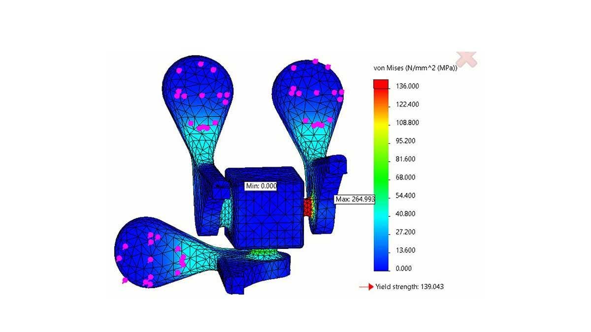
In this example, I am testing a compliant mechanism with three different sized connections. The maximum stress is located on the smallest connection, but I want to simultaneously prove mesh convergence on all the connections in one operation. Before I create the design study, I need to make sure my boundary conditions and mesh are solvable and give me intuitive results. With this first run, I want to troubleshoot any potential problems before I iteratively run the study. By the end of the process, we will prove that the solution is independent of the mesh in those areas of interest. Looking at the animation below, the results of a static study, I am comfortable with the reaction of the mechanism to the loading. This lets me be confident with my boundary conditions and component interactions.
Results of the simulation to validate boundary conditions and interactions.
Step Two | Create Sensors On the Entities Where You Want to Prove Convergence
In order to monitor the stress value, or whatever simulation result you want to prove convergence for, a Sensor needs to be created on the area of interest. I like to do this in the Model window and right-click the Sensors folder and “add sensor.”
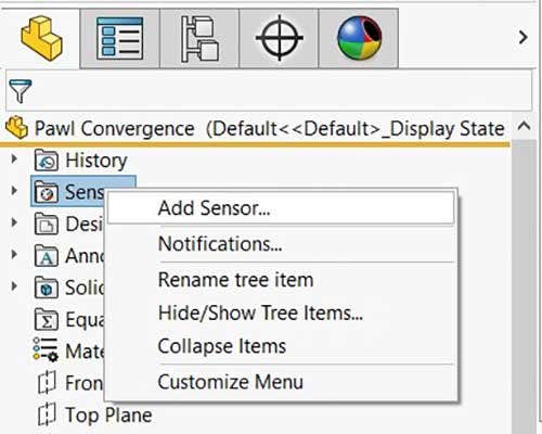
Adding a sensor by right-clicking the sensor folder in the feature tree.
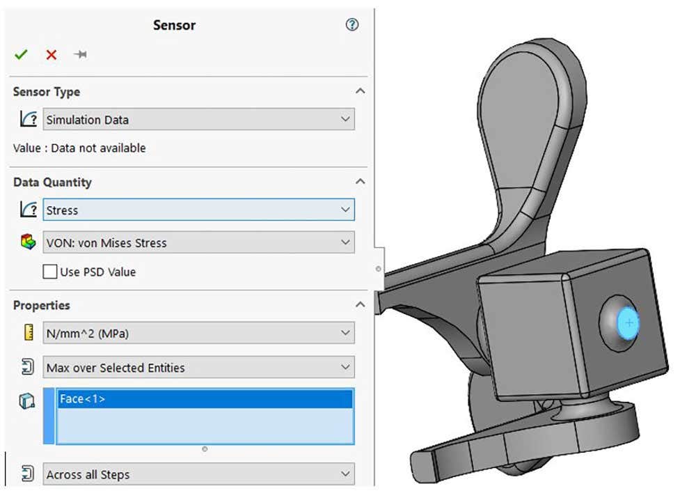
For the sensor type, choose simulation data and for the data quantity, choose whatever result you want to analyze. In this example, it is the Von Mises Stress. For the properties I want the sensor to find the maximum value over selected entities and select the two faces of the connection. This selection is only going to monitor the surface area of the connection, not the entire volume. Since the volume is in torsion, I can expect the maximum stress to be on the outside surfaces. The Sensor Property Manager can be seen below.
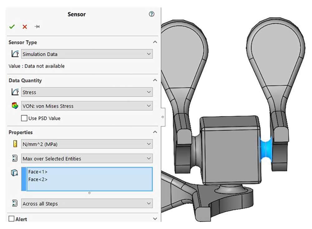
Property manager of the sensor used to monitor the 1/4″ connection.
If I wanted to monitor the cross-section of the connection, I would have to split the part into two in order to create a selectable area and then ensure that the parts had a bonded component interaction at the contact area so they behave as a rigid body. This can be seen below.
Alternate workflow displaying a sensor measuring the von Mises stress of the cross-sectional area of the connection.
Now that the Sensor is complete, I am going to rename it to make selecting it more intuitive and because it will be the title of an axis of the convergence plot. This process was repeated for all three connections. The Sensors folder ended up looking like this:
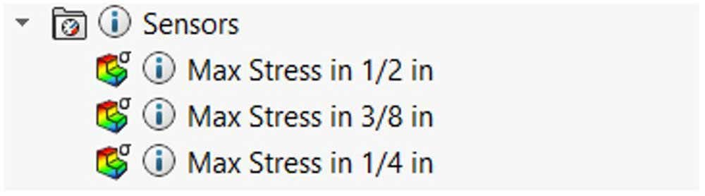
The sensor folder of the feature manager design tree displaying the logically named sensors.
Step 3 | Link the Mesh Control to a Parameter
In order to run a Design Study, there has to be a Parameter that is set as the variable to manipulate in the study. I want to link the Mesh Control to a Parameter. I will do this in the Mesh Control tool. Instead of a discrete value for the element size, I am going to link the value by selecting the drop-down arrow at the end of the text box, as seen below.
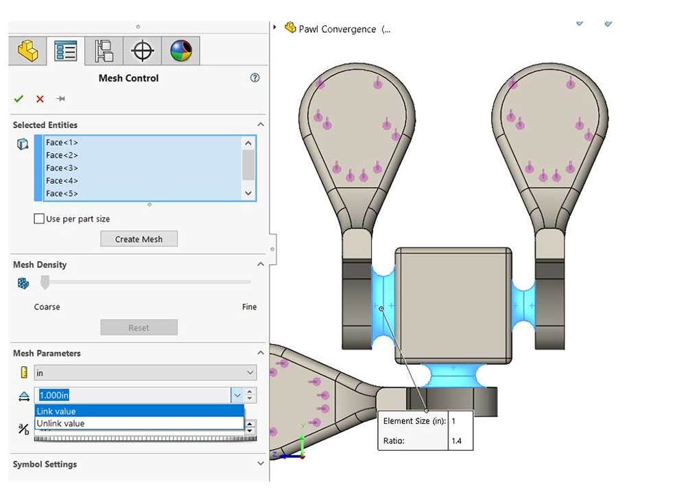
The mesh control property manager displaying the link value option.
Clicking Link value will open the Select Parameter window which is blank because I have no parameters yet. The Select Parameter window can be seen below.
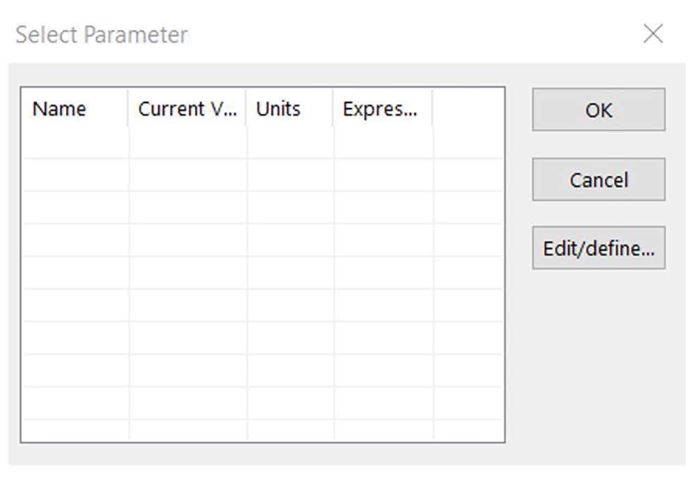
Select parameter window for linking a parameter to the mesh control element size.
If I click Edit/define the Parameters window will open where I will create the parameter. I will name it “Mesh Control” and select the simulation category and set an arbitrary value of 0.5 in. The Parameter window can be seen below. Hitting Ok will create the parameter.
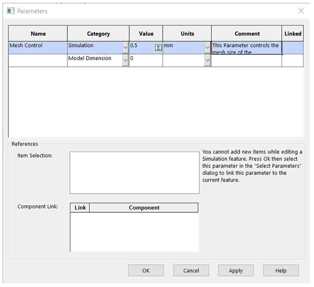
Parameter window where the mesh control parameter is created.
Selecting the Mesh Control parameter and hitting Ok again will link the element size to the parameter. We know it all worked out because the selection box is now grey signaling that it is linked to a parameter.
This parameter is what we will be manipulating in our Design Study to better understand how our mesh influences the solution. Our goal is to have no change in stress when the mesh gets more refined. This will prove that our solution is independent of our mesh and that the results have converged.
Step Four | Set Up the Design Study
Inside of the Design Study, the variable we want to manipulate is the Mesh Control Parameter which is linked to the element size of the mesh control on the areas of the pawl connections. Hitting the drop-down arrow under Variables the Parameters are listed and I will select the Mesh Control Parameter. The next column determines how the variable will be manipulated and I will choose Discrete Values as this allows me to enter in the numbers I desire. For the values, I will incrementally reduce the Mesh Control Parameter which will reduce the element size and refine the mesh in my area of interest. I will start at the global maximum element size of an inch and go all the way to a hyper refined mesh of 0.05 in and 0.01 in just for a proof of concept, but this is most likely going to be overkill. In this text box, I can ignore units and use commas to separate my discrete values. You can see the Variables set up of the design study in the image below.
Under the Constraints section, I will select the Sensors. This is where naming the Sensors starts to come in handy as it is very easy for me to tell what the Sensor is. I only want to monitor the Sensor so I will choose that in the next dropdown. I want to run the Mesh Control Simulation Study which I will select from the final dropdown. The Mesh Control Simulation Study is where the element size of the Mesh Control feature is linked to the Mesh Control Parameter. That was a mouthful, and I am beginning to regret my nomenclature. I will repeat this process for the two remaining Sensors so the Design Study looks like the image below and then run the Design Study.
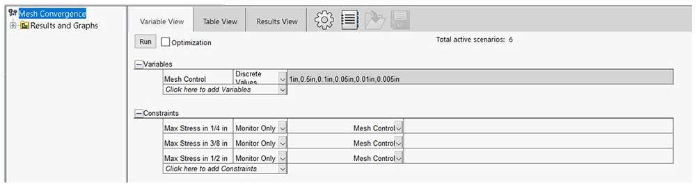
Competed design study set up to incrementally refine the mesh and prove stress convergence in the sensor areas.
Step Five | Results and Creating a Convergence Plot
Looking at the results on the Results View tab, as seen below, I can see the values fluctuate with about a two percent difference and I can draw the same conclusions from the values regardless of the mesh. The smaller connection will experience plastic deformation and not return to its original shape because the stress in that region is above the yield strength of the material.
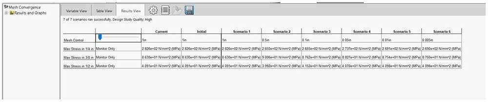
Results view of the design study.
Right-clicking the Results and Graphs folder, as seen below, I can create a Design History Graph where the scenarios are on the x-axis and the Sensors are on the y axis. The image clearly shows the convergence of the stress values. The horizontal line is a great sign that the stress values are not changing as the resolution of the mesh increases. This can leave me to conclude that my results in the connection area are independent of my mesh and I can use one of the coarse meshes and still get accurate results.
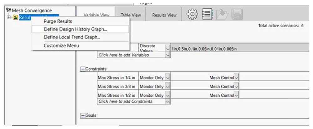
Defining a design history graph.
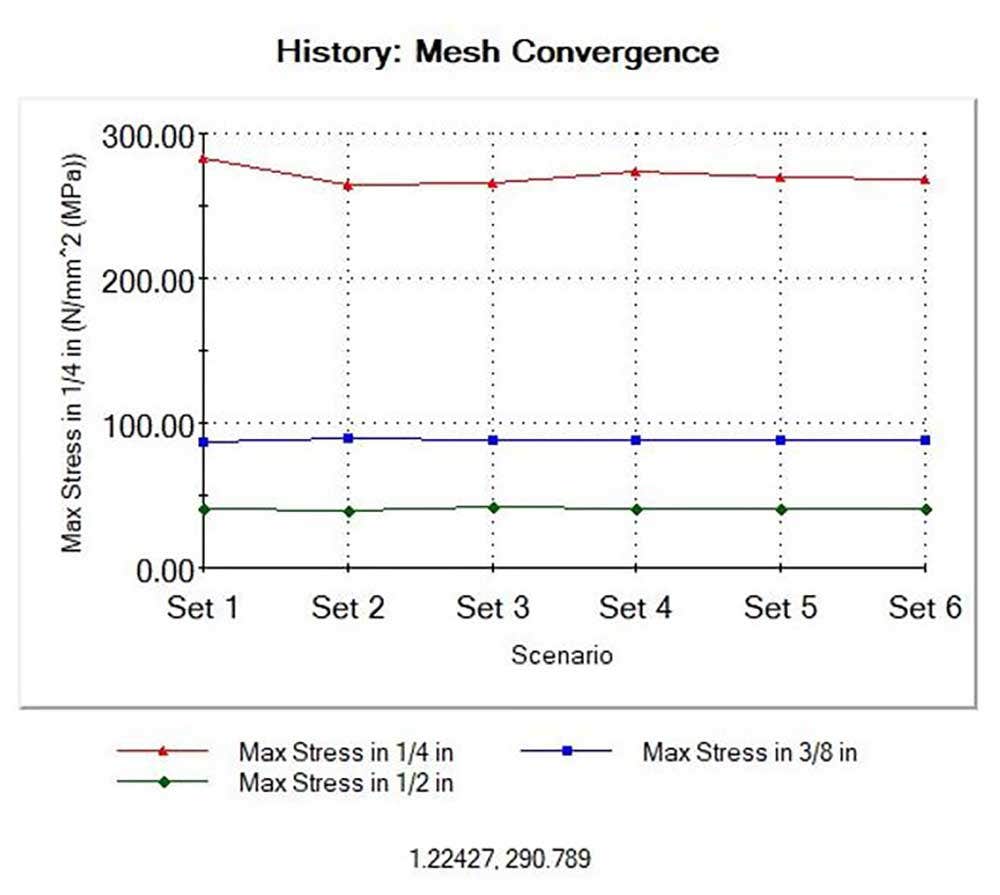
Design history graph displaying the convergence of the stress value on the connection areas.
Conclusion
Using a Design Study to create a convergence plot is an alternative method to the automated tools in SOLIDWORKS. It is not restricted to element or study type, you can see all the results in one window without the need for numerous simulation study tabs, and you can create convergence plots without compiling data from different studies.
Check out our website for more information on SOLIDWORKS Simulation and if you have any questions, contact us at Hawk Ridge Systems today. Thanks for reading!


