Getting started with SOLIDWORKS can be a challenge, especially for new users coming from 2D CAD programs. We’ll cover the basics of the SOLIDWORKS user interface, giving you the tools and understanding that you’ll need in order to be prepared for your first design, tutorial or training class.
When SOLIDWORKS initially starts, you’ll be presented with the Welcome screen. This new dialog for SOLIDWORKS 2018 provides several tools for getting started, including buttons to begin a new part/assembly/drawing, browse for an existing document, open a recent document, or access recent folder or SOLIDWORKS resources.
To get started, click the Part button. This will open a new part document, and the rest of the user interface will be revealed.
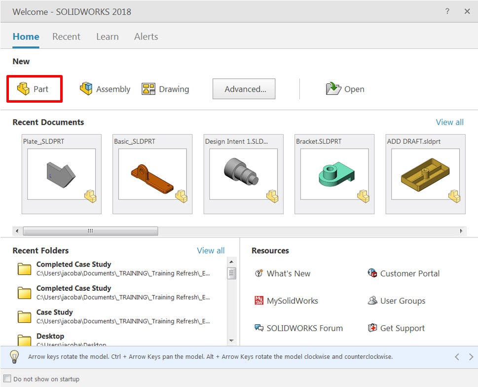
Welcome screen for SOLIDWORKS 2018
If you do not see the welcome screen, or are using an earlier version of SOLIDWORKS, click the New button on the standard toolbar at the top-left corner of the screen to open the New SOLIDWORKS Document dialog. From here, click the Part option and select OK. If the dialog that appears does not look like the one shown below, click the Novice button at the bottom-left of the dialog.
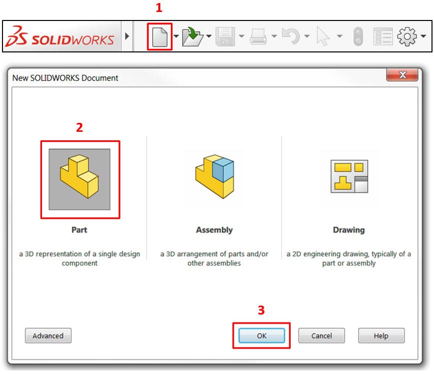
Starting a new part document (SOLIDWORKS 2017 and earlier)
Once the new part document has been opened, the interface will look like the figure shown below. There are six unique areas of the user interface which every new user should be familiar with, and we have labeled them in the image for convenience.
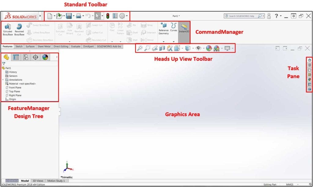
SOLIDWORKS user interface
Standard Toolbar

The Standard Toolbar contains basic commands including New Document, Open Document and Save Document. Additionally, at the right end of this toolbar, a gear icon is available which will open a System Options dialog, where a variety of settings can be changed. Hovering the cursor over the SOLIDWORKS icon will reveal several drop down menus that contain all available commands, including a Help drop down menu where tutorials may be accessed.
Remember, hovering the cursor over any icon in SOLIDWORKS will display a tool-tip explaining the command or tool!
CommandManager
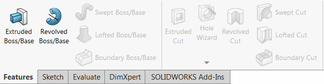
The CommandManager is a context-sensitive toolbar that provides different sets of commands based on the tab that is selected directly below it (Features, Sketch, etc.). This is the primary area where users begin commands to create sketches, add/remove material, or evaluate models, among many others. In many cases, SOLIDWORKS will automatically switch to the appropriate CommandManager tab when changing modes, however, it may be necessary to manually switch between tabs by clicking on them.
Not all available tabs are shown under the CommandManager by default. If working in Sheet Metal or Weldments, for example, right click an existing tab and select the desired tab from the list. This will add the tab permanently.
Additionally, not all commands are available in the CommandManager tabs by default. To customize your CommandManager with extra commands, consider taking a look at this CommandManager tutorial. Otherwise, all commands can be accessed through the file drop down windows. To reveal these drop down windows, hover the cursor over the SOLIDWORKS badge at the top-left of the screen. In these menus, you will find all the commands and options available in SOLIDWORKS. These menus can also be made permanently visible by clicking the pushpin icon just to the right of the Help drop down.
Finally, it is possible to search for commands, provided you know the name of the command. At the top-right of the interface exists a search bar, which by default allows the SOLIDWORKS help file to be searched. Click the down arrow on the right of the search bar and select Commands to enable command search. Search results can be clicked to execute the command, or the eyeball icon can be selected to automatically show the command’s location in the user interface. Additionally, commands can be dragged and dropped directly onto the CommandManager from the results list.
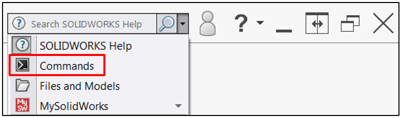
Searching for commands
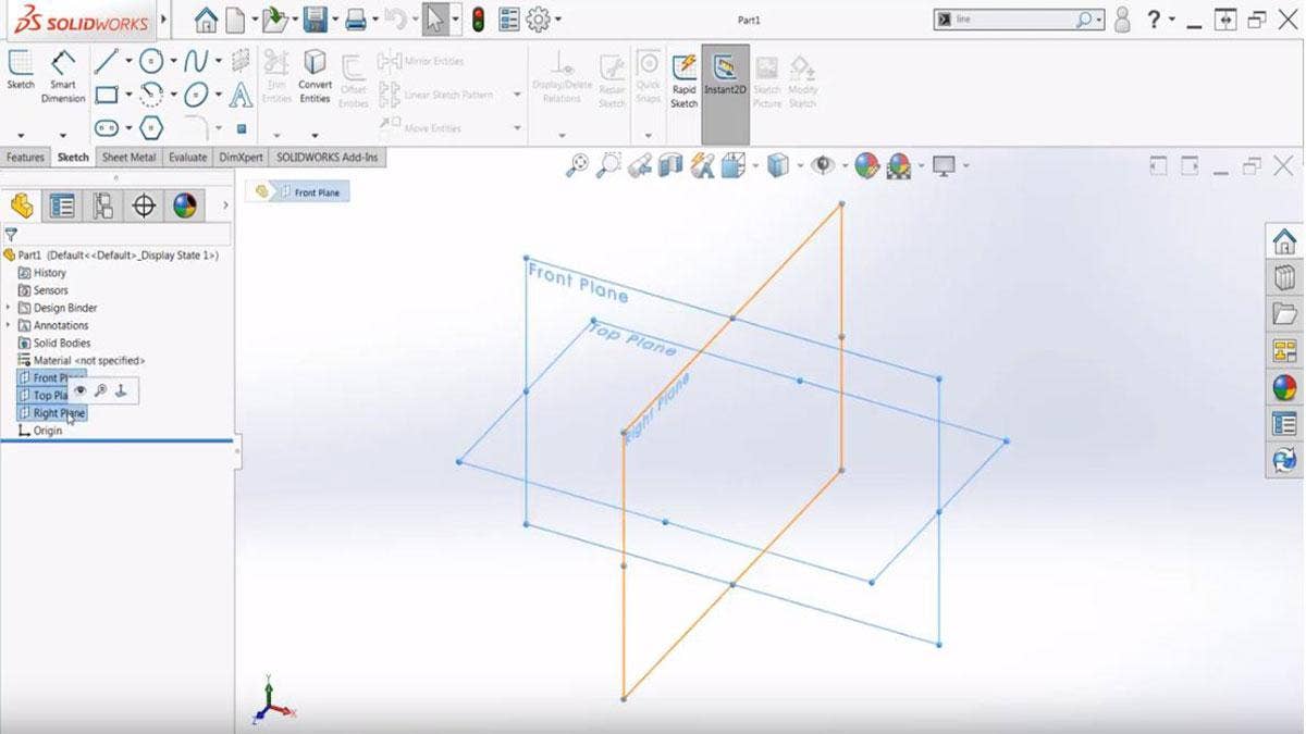
FeatureManager Design Tree
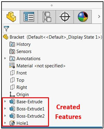
The FeatureManager Design Tree is a chronological hierarchy of all the sketches and features that have been created or applied to the model, appearing just after the Origin. This section of the interface is exceptionally important, as it is where many editing operations originate. Here, you will also find three default planes, which act as the base geometry for (at a minimum) your first feature.
This area of the user interface will temporarily change to a PropertyManager when creating a new feature or during various other operations. This is the default behavior of SOLIDWORKS, and the FeatureManager Design Tree will return once the feature has been completed.
The tabs at the top of the Design Tree are used to navigate to other interfaces that use the same space; if another interface is accidentally shown, simply click the first tab to return to the Design Tree. If the interface is completely hidden, be on the lookout for a small tab on the left side of the screen. Click this small tab to return the Design Tree to view.
Heads Up View Toolbar

This transparent toolbar at the top of the graphics area provides a number of controls for manipulating the colors and appearances of your designs as well as your perspective of them. You may also here this toolbar referred to as the Heads Up Display Toolbar. Commonly used functions here include fitting the model to the screen, changing view orientation, changing the display style (shaded with edges, wireframe, etc.) and applying colors/appearances to designs. Remember, hovering the cursor over any of these commands will display a tool tip explaining it!
Task Pane
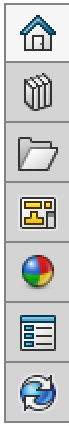
The Task Pane contains several tabs that all serve different purposes. Depending on other applications you may have installed in addition to SOLIDWORKS, you may have a greater or lesser number of tabs than are shown here. While the Task Pane has a number of great tools within it, they are not required for basic use of SOLIDWORKS, and will not be covered here.
Graphics Area
This is the main area of the screen where models and drawings are viewed, controlled, and selected. Controlling model orientation/zoom and learning to properly select entities are critical to effectively designing with SOLIDWORKS, and are two of the first aspects that new users should become comfortable with. To follow along with this section, use the open command to open an existing SOLIDWORKS model.
Left click an entity in the graphics area to select it. Alternatively, left click and drag the cursor to create a selection window. Right click on an entity to display a shortcut menu and a context menu, which contain a variety of commands applicable to the selected entity. The context menu is the smaller menu that appears with only icons; the shortcut menu is the larger menu that contains both icons and text.
To rotate a model, click down on the center mouse wheel (or center mouse button if you do not have a wheel) and drag the cursor. This will rotate the view freely in space, but does not change the coordinates of any geometry. If rotation is activated while hovering the cursor over existing geometry, that point will be fixed in space during rotation. To pan the view, hold the Ctrl key and follow the same steps.
Scroll the center mouse wheel to adjust the level of zoom in the model. By default, scrolling forward will zoom out, while scrolling backward will zoom in. This behavior can be reversed by changing the settings available in the View category of the System Options. Alternatively, if you do not have a center mouse wheel, hold the shift key and click and drag the center mouse button to zoom. This method also works with a center mouse wheel. For the best zoom performance, it is important to remember that when using the mouse wheel to zoom, the model will be zoomed in/out with respect to where the cursor is on the screen.
User Interface Basics Tutorial
After looking at the key elements of the user interface to get you acquainted with SOLIDWORKS, you can get off to a running start with your first model. Visit our website to learn more about SOLIDWORKS CAD, or contact us at Hawk Ridge Systems today. Thanks for reading!


