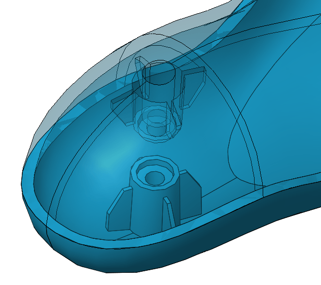
The following blog is the process of how to use the Mounting Boss command on your model. This is the perfect feature for a plastic injection molded part, or any part requiring geometry for your hardware mounting system. Why model a complex extrusion for your hardware, when the mounting boss command can automate this process for you?
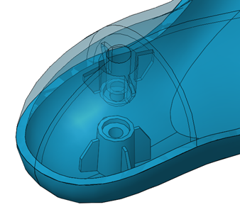
The mounting boss feature can be found under Insert> Fastening feature > Mounting Boss. The mounting boss command requires a face or 3D point on which to locate the geometry on. The procedure which I have found helpful is to select a face in the general position that you want the boss to go. Then, edit the 3D sketch that the feature creates to more precisely locate the boss.
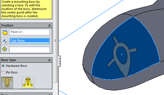
Once this first reference has been selected, the user will need to select a direction for the extruded boss. This can be done using a reference plane. In the graphic above, I selected the top plane as my direction. There is another box below my direction selection waiting to be populated (this box has multiple circles as an icon). This portion of the feature is looking for a circular edge to position the mounting boss in relation to. This selection is perfect for your second mounting boss feature, that way the user can insure that the hardware holes will be aligned in positioning.
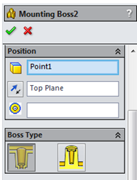
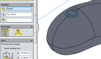
After the previous selections, the user then needs to select the graphic under the boss type portion of the command. The two selection options available are “head” or “thread”. The head option will enable you to have a recessed cavity in which your hardware can sit in the bottom of. The thread option is creating geometry in which to add a threaded portion for your hardware to grab.
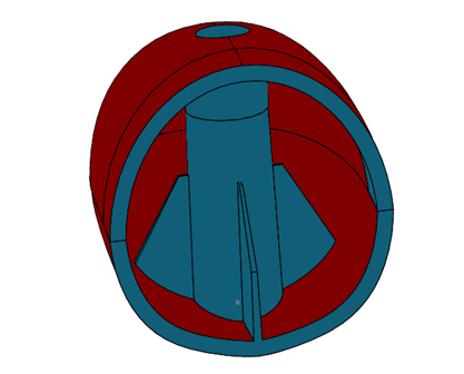
After selecting your location and type of mounting boss, there are very user friendly inputs for the precise geometry for your mounting boss. As you will notice from the graphic below, you can either enter the boss height or select the mating face. Entering the boss height will give the user full control over all of the geometric dimensions. The geometry input is very extensive, giving the user full control over dimensions, such as input angles for draft. At the same time the geometry input is very simple, meaning every dimension is graphically described for what input the feature is looking for. Selecting mating face will eliminate the user’s ability to select the dimension for “A” (see graphic below). The reason this disappears is because the “A” represents the overall height, and by selecting a face SolidWorks automates this height selection. In the bottom of the boss section of the command, there is a selection to turn on and off a clearance value for the boss height. This clearance value is used for when a user wants to build in a gap to better fit their model for production.

Keep an eye out for more great SOLIDWORKS content on the blog and subscribe to our YouTube channel.
If you’d like to see a video using this technique, please click here.
