A compliant mechanism is a flexible device that achieves force and motion transmission through elastic body deformation. A compliant mechanism gains its motion from the relative flexibility of its members rather than from rigid-body joints. The fact that a complaint mechanism uses the elasticity of the material to move makes it perfect for a linear static study. In a SOLIDWORKS Simulation linear static study, the results have to stay within the linear elastic range of the material or return to its original shape once all loading is stopped, making this the perfect domain for compliant mechanisms.
Problem Statement
This article will take you through the simulation process used to validate a compliant mechanism. For this example, the pawl for a ratcheting gear system will elastically deform to release the gear as seen in the figure below. Normally, a pawl would have a spring or lock to keep it in place, but we are going to use the elasticity of the material instead.
Elastic deformation of pawl to release the gear.
The challenges in this design were having enough material at the compliant connection point to not induce yielding but not too much material that it was so stiff that an inhuman amount of force was required to move it.
The pawl is connected to the mechanism by a cylindrical extrusion as seen in the figure below. As the thumb button pressed the pawl will release, caused by the torsional displacement in the cylindrical extrusion.
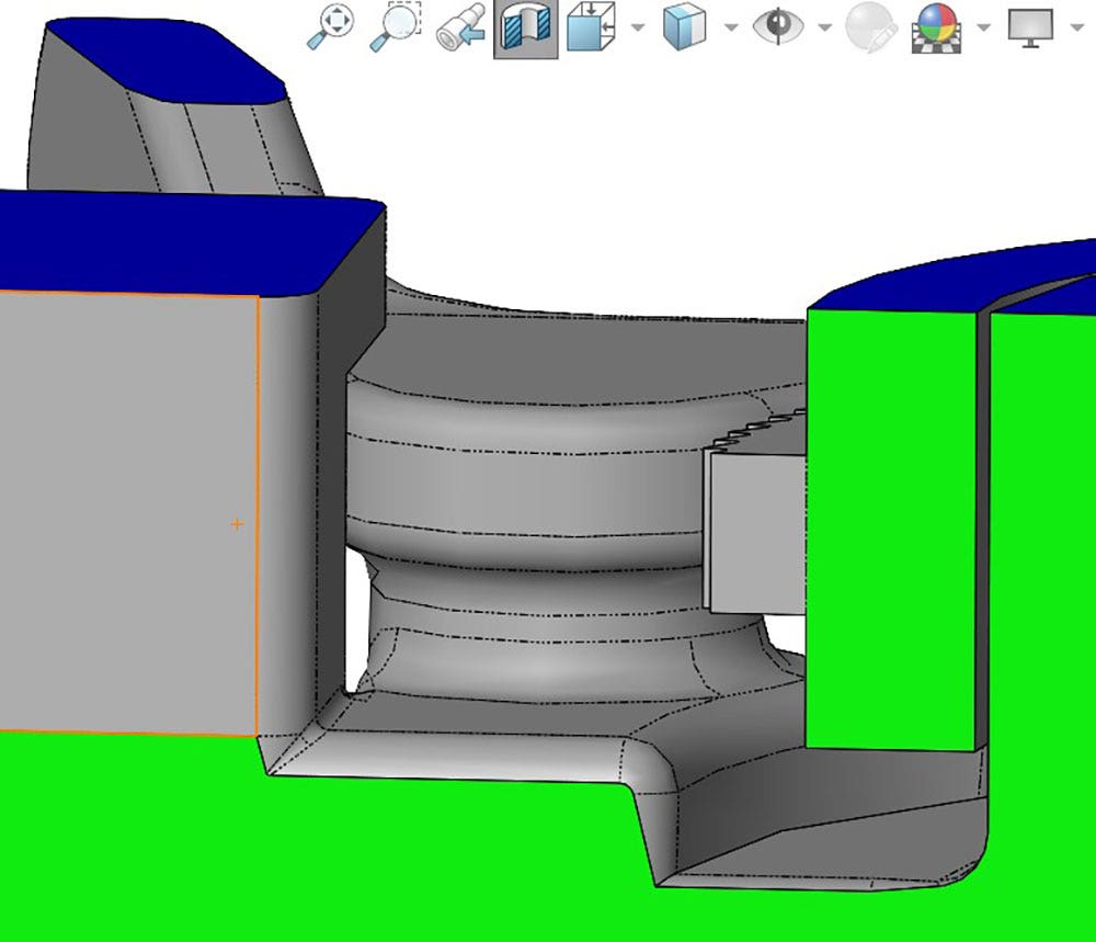
Cylindrical extrusion of the pawls compliant connection point.
Will the Compliant Mechanism Yield If Pushed to Maximum Range of Motion?
The way that I approached this problem was to use a prescribed displacement to see how much force was needed to push the pawl into contact with the part, which would be its maximum allowable displacement. This would be a worst-case loading scenario and if the compliant mechanism can withstand this then normal operation will be fine.
Since I did not know how much force to apply but did know how far I wanted the pawl to displace, I used the prescribed displacement fixture. This will use a boundary condition to rotate the blue face approximately four degrees about the axis of the pink face, as seen in the image below. In order to prescribe a rotational displacement, I had to change from the cartesian coordinate system to a cylindrical coordinate system. This was done by choosing a cylindrical face as my reference direction, the pink selection box, in the figure below.
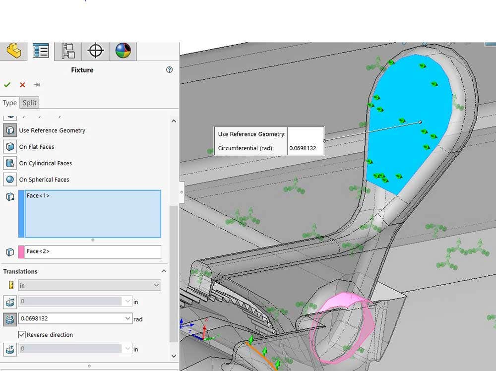
A prescribed displacement being applied to the compliant mechanism.
In the simulation, the perfect amount of force will be applied to displace the selected face the prescribed amount. That deformation will cause internal stresses and strains which will be compared to the material model. After a few more fixtures were added to keep the model restrained the study could be run.
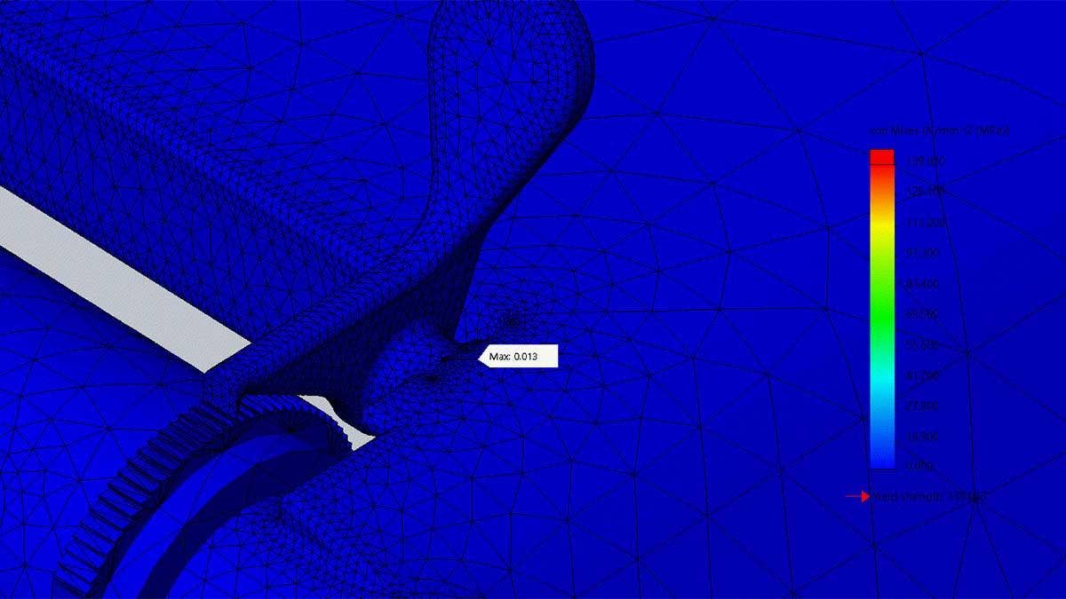
This study was intended to test the range of motion of the compliant mechanism and determine the amount of force required to max it out. The failure criteria I used was the flexural strength because the material is not isotropic due to the printing process, and this is the strength data I have for the 3D printed material I am using to manufacture this part. The maximum allowable stress is going to be 65 MPa with an allowable strain of 15 percent. As we can see in these images, when the pawl is pushed to the maximum position the stress and strain are below the material limits.
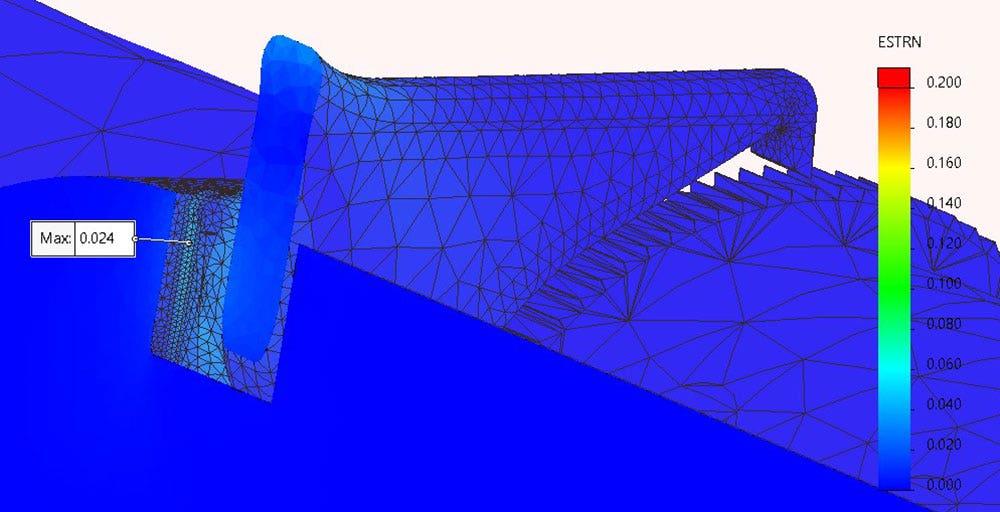
Maximum strain on the compliant mechanism when pushed to the maximum position.
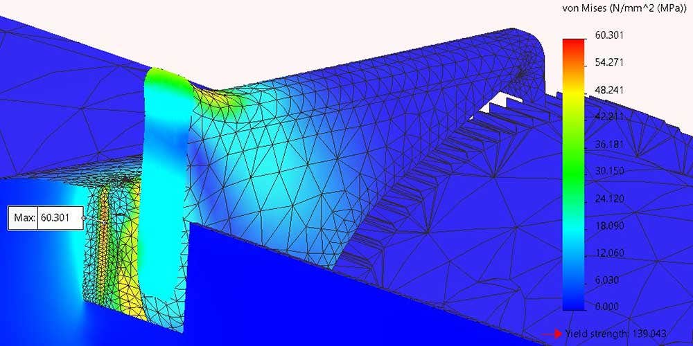
Maximum stress on the compliant mechanism when pushed to the maximum position.
To understand how much force is required to put the pawl in this maximum position, SOLIDWORKS Simulation has the ability to list resultant forces as seen in the figure above. The result force tool will tell you how much force is required to ensure a fixture stays fixed when you are evaluating the reaction forces. In order to force the pawl into the maximum position, a total of 450N is required. This number is on the higher end of the human grip capacity but that is okay because this amount of force is not required to release the pawl.
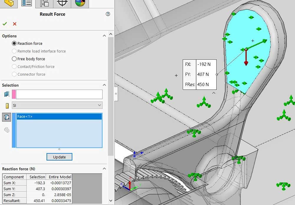
The resultant force required to put the pawl in the maximum position.
From these studies, we can conclude that the compliant mechanism will not plastically deform or yield when it is put through its maximum range of motion.
How Much Force Is Needed to Release the Gear?
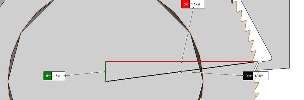
In order to answer this question I first needed to know how far the pawl had to displace to release the gear. I did that by measuring the distance from the center of the gear to the tip of the pawl tooth, and then subtracting the radius of the gear, as seen in the images below. The amount the pawl needs to move to release the gear is approximately 0.03 in.
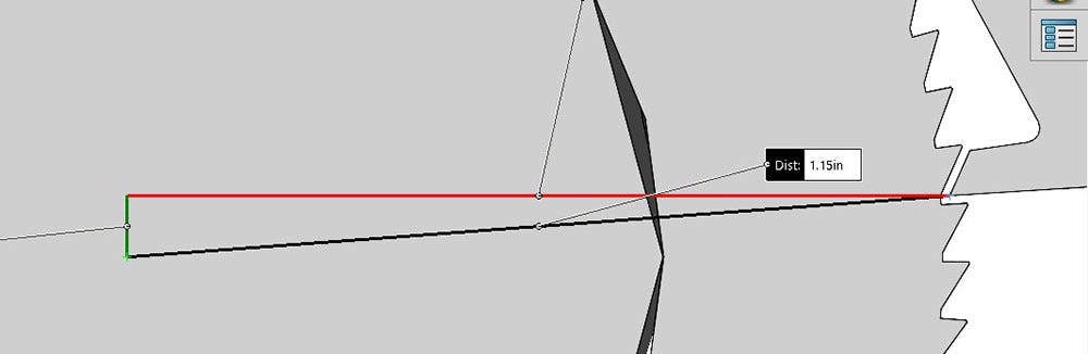
The distance from the center of the gear to the tip of the pawl tooth.
The maximum radius of the gear.
A parametric design study was used to find out how much force is required to create the clearance for the pawl to release the gear. A thumb force was created which was linked to a simulation parameter and a sensor was created to measure the radial distance from the pawl tip to the center of the gear. To create a sensor or plot that can measure a radial distance, you have to choose an axis as a selected reference for the displacement in the x-direction.
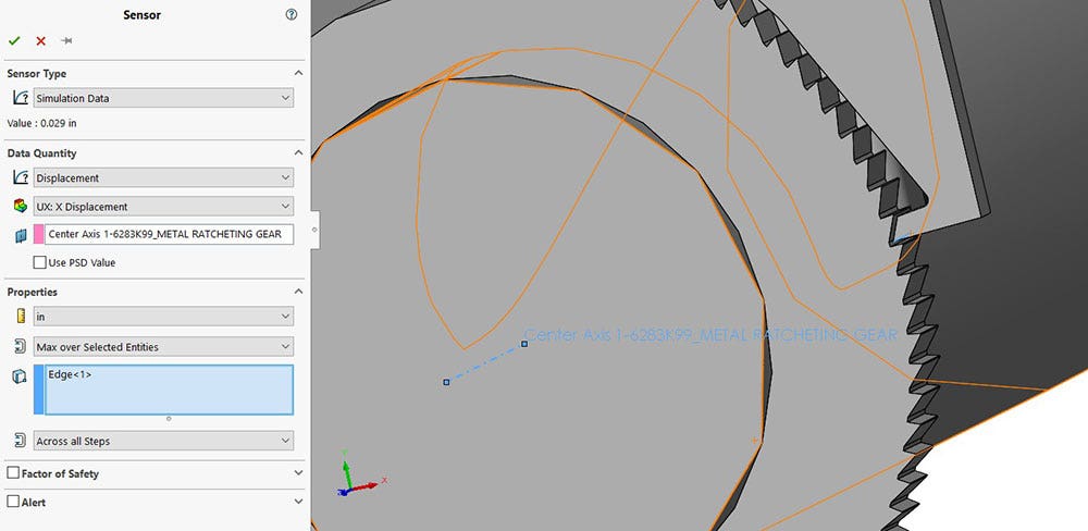
Creating a sensor to monitor the radial displacement from the center of the gear.
Setting up the design study was the quickest way for me to find the required force to release the pawl. To start, I varied the thumb force in a range of 50N to 200N with a step size of 50N and set the goal to have the pawl tip displace 0.03 inches in the radial direction. This set up ran four scenarios as you can see below.
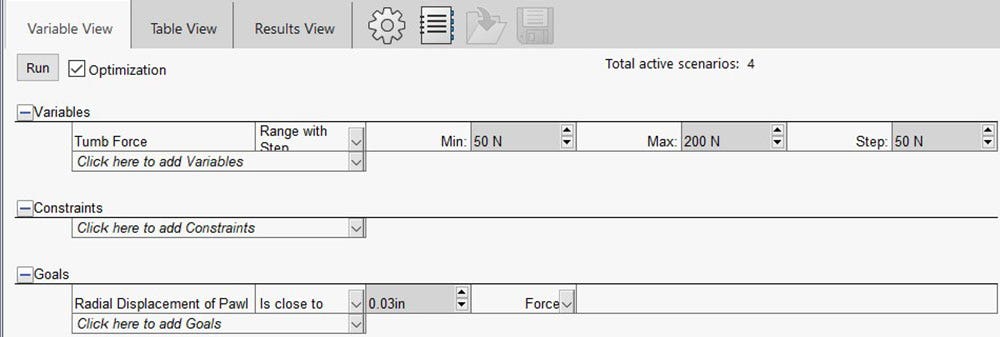
Design study set up with the goal of finding a force that will cause the pawl to displace 0.03 inches in the radial direction of the gear.
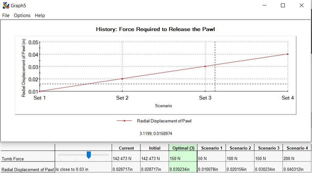
The design study saved me from having to do a trial and error approach to find the force required to move the pawl. From the results in the image below, we can determine that about 150 N of force is required to move the pawl enough to release the gear. This amount of force is easily achievable with a human grip.
Summary
In conclusion, we used SOLIDWORKS Simulation to validate a compliant mechanism. We found that if push the limit of its motion the material will not yield and that the human hand can release the mechanism as intended.
Visit our site for more information on SOLIDWORKS, and be sure to contact us at Hawk Ridge Systems today if you have any questions. Thanks for reading!


