In the
first article
in this three-part series, we discussed how the new Style Spline (Bézier
curve) in
SOLIDWORKS 2014
is different from the existing spline type (a B-Spline). In the
second article
in the series, we talked about why Bézier curves matter, and where, as a
SOLIDWORKS user, you would want to use them. In this article, we get even
deeper into the functionality of the Style Spline.
The Style Spline in SOLIDWORKS 2014 has some additional commands and options
of which you’ll want to be aware. Knowing that they exist, what they do, and
how to use them will help you create and shape the curve faster and easier.
First, when sketching the curve (which is done by placing its CVs) it’s not
only possible to infer tangency at the first endpoint, but you can also infer
Equal Curvature. The first CV sketched, which is the curve’s first endpoint,
controls the first degree of curvature called contact, or C0 continuity. The
2nd CV controls the 2nd degree of curvature, which is
tangency, also called C1 continuity. The 3rd CV controls the 3rd
degree of curvature, or Equal Curvature, also called C2 continuity. Therefore,
you will see a 2nd inference line when sketching the 3rd
CV of the curve. If you snap to it, an Equal Curvature constraint will be
applied at that endpoint once the curve is complete. No other curve currently
in SOLIDWORKS can do this. Not too shabby!

If the Style Spline terminates on the endpoint of another entity, hold down
the [Alt] key as you double click to end the curve in order to automatically
apply a tangent relation at that endpoint, otherwise it will be coincident. If
you want Equal Curvature at that endpoint, you will still need to apply this
manually.
When sketching the curve, automatic relations between the CVs and other
geometry in your sketch or model are not created. The only exception is at the
endpoints of the curve. The reason is due to the fact you are sketching the
curve by its CVs; the shape of the curve you end up with most likely will not
be final. The CVs need to be free so that the user can drag them to keep
shaping the curve. If desired, you can manually constrain the CVs
after the curve has been completed. You can do this with relations,
dimensions or both. You can also constrain the construction lines between the
CVs.
When dragging CVs to shape the curve, hold down the [Ctrl] key if you don’t
want them to snap to other geometry in your model. This temporarily disables
automatic relations, and will prevent the CV from accidentally getting locked
to a vertex, line, or edge in the background.
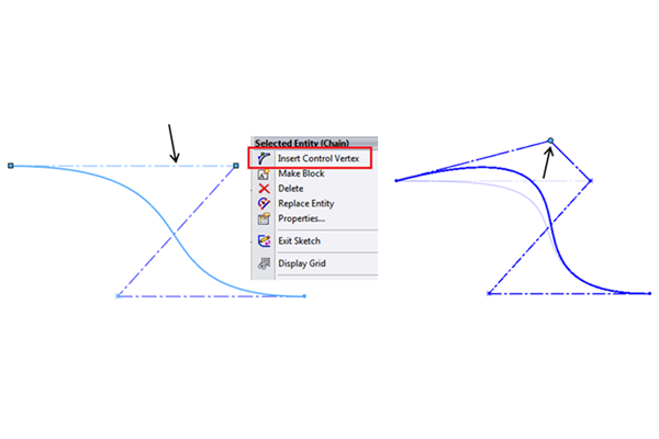
Once you’re finished creating the curve, you can still adjust the degree of
the curve. By doing this, you are adding or removing control. This can be done
via a spin box in the PropertyManager, or manually by adding (RMB > Insert
Control Vertex) or deleting CVs one at a time on the polygon. However, if any
CV (other than endpoints) is constrained at all, the spin box will be greyed
out. This is to keep the curve from jumping abruptly since all the CVs are not
free to adjust in order to maintain shape. In this case, you can still control
curve degree manually by deleting or adding CV’s via the RMB menu command.

There is a checkbox in the PropertyManager called Local Edit. This setting is
to aid the user when working with multiple Style Splines that are connected,
yet not fully constrained. You may have one or two main curves that represent
the primary surfaces on your model. Connected to those curves may be other,
smaller curves for some secondary surfaces. There are times, when shaping the
secondary curves, you may not want to affect the shape of the larger curves.
Enabling the Local Edit setting on a particular Style Spline will prevent any
CV adjustments from affecting other Style Splines to which it is connected.
This option is currently only available for Style Splines.

We’re also happy to report that this curve works in 3D Sketches as well.
Creating it in 3D is just as easy and works the same way as creating a series
of lines. When dragging CVs to shape the curve, we strongly recommend that you
use the 3D triad (RMB > Show Sketcher Triad). This helps greatly by
constraining the free drag to X, Y, or Z directions, or XY, YZ, and XZ planar
directions. You can assign a hotkey to the triad to speed up your workflow.
Better yet, add it to your
Mouse Gestures.

Hopefully now that you’ve digested this series of articles, you can fully take
advantage of the benefits of the Style Spline and recognize the right
situations to use it.
Learn More:
Read Taking a Deep Dive into the Style Spline in SOLIDWORKS – Part 1
Read Why Bézier Curves Matter – The Style Spline in SOLIDWORKS – Part 2


