When designing sheet metal parts, it’s very common to have an asymmetric part
that requires an exact opposite hand (mirrored) version. SOLIDWORKS has always
had a great part mirroring function that accomplished this in no time,
eliminating the need to completely create the new part from scratch. However,
if the part was made with Sheet Metal features, the manufacturing information
was not transferred to the mirrored part. This information is critical when
documenting the mirrored part on a production drawing. Introduced in
SOLIDWORKS 2015, when creating mirrored versions of sheet metal parts it is
now possible to transfer the sheet metal and flat pattern information from the
original part to the mirrored part, saving you a huge amount of time during
the drafting phase.
The manufacturing information that can be transferred to mirrored sheet metal
components includes:
- Flat pattern geometry • Bend lines
-
Fixed face •
Bend parameters -
Grain direction • Sketch
transformations -
Faces to exclude • Forming
tool information
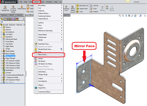
Let’s take a look at the process to see how this is done. To create our
mirrored part,we select the mirror face, then click
Insert > Mirror Part.
So far, so good. Nothing new to the workflow yet, but now here’s where things
get interesting! In the PropertyManager, under Transfer,
select:
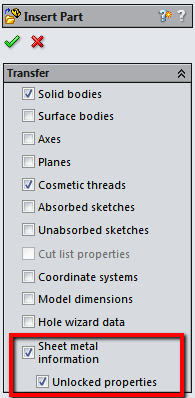
Sheet metal information: Transfers the sheet metal and flat
pattern information from the original part to the mirrored part, such as fixed
face, grain direction, bend lines, and bounding box.
Unlocked properties: This option allows you to edit the sheet
metal definition in the mirrored part, which will update the cut list
properties. This applies only to new feature properties, not the imported
mirrored body.
Now complete the operation by clicking the green check and let’s see what kind
of goodies came over into our new, mirrored part. The new part retains the
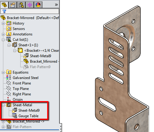
sheet metal information from the original part. If we expand the
FeatureManager, we can access all of the transferred properties and
information. First, in the “Sheet-Metal” folder, we can see that we have the
Sheet-Metal feature, which is editable (via RMB or Context Toolbar) because we
unlocked the properties when we created the part. If we needed to change out
the Gauge Table, thickness and bend parameters, and Auto-Relief settings,
that’s now possible.

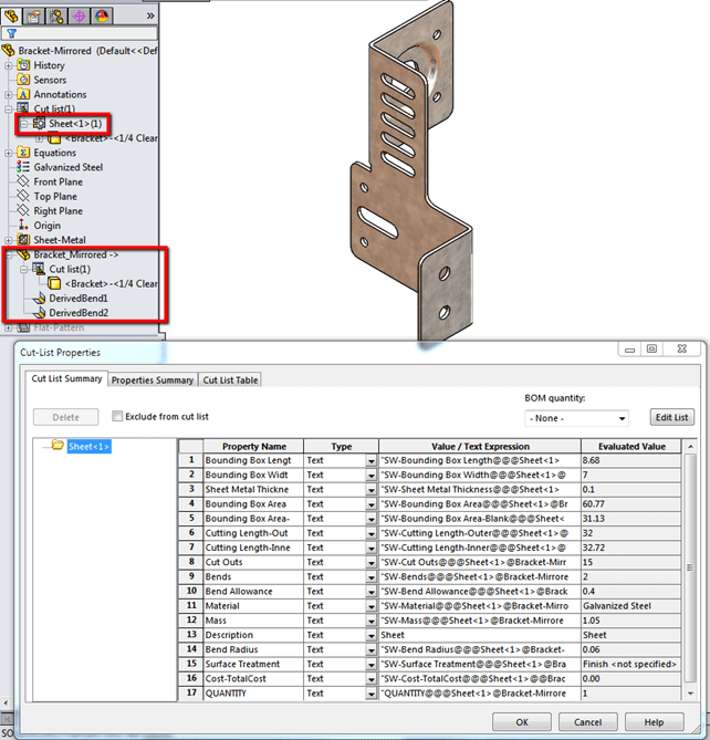
Next, the Mirrored Part feature contains Cut List and bend information. The
Cut List properties are available. Note: if you RMB on the body feature in
this folder and select Edit Definition, you are taken back to the Transfer
property manager in case you need to include or exclude certain things from
your model.
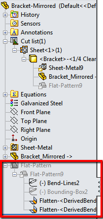
And lastly, the “Flat-Pattern” folder contains the flat pattern information.
You can edit the Flat-Pattern feature to change things like the Fixed Face,
Corner Treatments, Grain Direction, and Faces to Exclude. The Bend Lines and
Bounding Box sketches are also contained here, in addition to the Flattened
Bends. Just like a native sheet metal part!
All of this information in the mirrored part makes the drafting side of this
design much, much easier. The information for Bend tables, Cut Lists, Flat
Patterns, etc. are all contained in the part and can be used on your
production drawings to fully detail the design in a much more automated way
without having to recreate things that were already present in the original
part.


