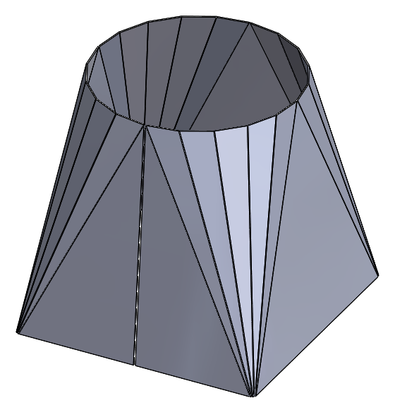
SOLIDWORKS gets used in a lot of fabrication shops and a question that often comes up is how to create a model and generate a flat pattern for a sheet metal square to round.
 |
It’s actually pretty easy to do this using the lofted bend feature, but there are a few tricks to be aware of. To start, 2 sketches on 2 different planes are needed to define the ends – a square and a circle.
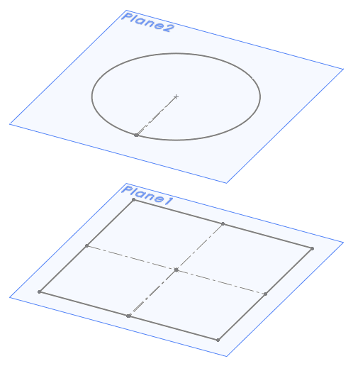 |
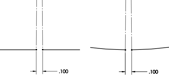
Seems obvious. However, these need to be open profiles so each sketch needs a small gap. Construction lines and relations can help keep things symmetrical.
 |
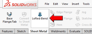
With these sketches in place, the Lofted Bend can be created.
 |
The manufacturing method should be set to Bent. This will give a more accurate model and flat pattern for fabrication with a press brake. The Faceting can be defined by a value for the Chord Tolerance, Number of Bends, Segment Length, or Segment Angle. (If you decide you want to use the Formed manufacturing method option, all sketch entities need to be smoothly connected, so sketch fillets are required on the square.)
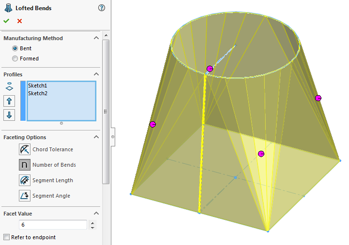 |
When selecting the sketches, it’s important to click on corresponding locations on each sketch. In other words, if you click on the right side of the square, click on the right side of the circle. If this isn’t done correctly, the loft will be misaligned and a pair of crossed yellow lines will appear instead of a preview.
 |
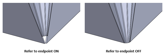
The Refer to endpoint option specifies whether the created bends refer to a sharp corner or adjacent bends are used to form an approximated arc in the corner.
 |
The sheet metal thickness, bend radius, and bend allowance need to be properly specified as usual. And that’s it – just one lofted bend feature is all that’s needed to model a sheet metal square to round. Since the bent manufacturing method option was used, the flat pattern – complete with bend lines – can be generated the same as any typical sheet metal model.
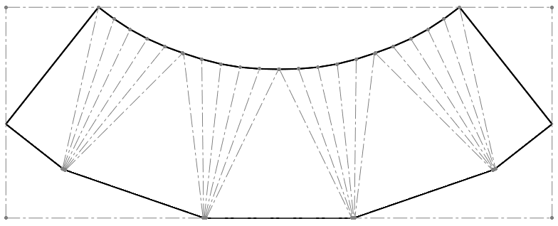 |
The lofted bend feature also works with sketches on non-parallel planes and shapes other than squares and circles, so there’s quite a bit of flexibility to make some interesting shapes.
 |
For more information, check out our YouTube channel, get a SOLIDWORKS 3D CAD quote or contact us at Hawk Ridge Systems today. Thanks for reading!


