Are you dedicated to creating your designs by hand? Whether it’s on a napkin
or a sheet of paper, some people prefer to draw out their designs before
starting it in SOLIDWORKS. In this blog, we’ll show an example of how to
insert a picture and use it to create a 3D design.

We can create a 3D model from a picture by inserting it into a
sketch in SOLIDWORKS. SOLIDWORKS is capable of inserting
.bmp, .gif, .jpeg, .tif, .tiff, .wmf, .png, and .psd file types onto sketch
planes, where you can then use the sketch tools to trace the geometry. Once
the geometry has been traced, you can then fully define the sketch and use it
in the same manner as any other sketches in SOLIDWORKS.
We’ll begin by starting a sketch on the Front Plane and inserting an
image. To do this, go to
Tools>Sketch Tools>Sketch Picture and select your
image. In the Sketch Picture PropertyManager, a
scale tool is available to control the scaling of the image.
If the width or the height of the design is known, the
scale tool can be used to make the image true-to-scale. For
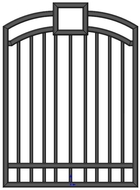
the image shown below, we’ll drag the endpoints of the
scale tool to the position of the known dimension – in this
case, the width of the gate. This activates the Modify toolbar, allowing us to
assign a dimension to the on-screen scaling line. In this case, the width of
the gate is 4 feet.

Additional tools are available to help translate or rotate the image to your
liking. Additionally, the image can be dragged to the desired location in the
graphics area to manually place it. In this case, we’ll position the picture
so that the origin is coincident to the bottom center of the image.
Now that the image is scaled and positioned correctly, the available sketch
tools can be used to create a sketch, tracing the image. As with any sketch in
SOLIDWORKS, sketch relationships and dimensions can be added to fully define
the geometry. Keep in mind, however, that the accuracy of the resulting sketch
will be dependent on the quality and orientation of the image. Some adjustment
may be necessary in order to get the geometry lined up precisely.

Once we’re done creating the sketch, features can be added as necessary to
create the 3D model. For this particular example, we’re going to add
Structural Members to our design, via the available
Weldments tools.
Note: While a variety of weldment profiles are available in SOLIDWORKS by
default, consider downloading complete libraries of profiles available in
the SOLIDWORKS Content section of the Design Library if you
frequently use weldments in SOLIDWORKS. Consider looking at our video on
Weldment Profiles here
for additional information.
By quickly and easily inserting an image as a sketch picture in SOLIDWORKS,
we’re able to take our design from an image to a fully-featured model. Now,
those of you who prefer beginning your ideas on paper can leverage those
hand-drawn sketches or images to create SOLIDWORKS models from them.
Additionally, if your images are typically simple and high-resolution,
consider having a look at our video on the Autotrace command for sketch
pictures here.
For more information, check out our YouTube channel, get a
SOLIDWORKS quote or contact us at Hawk Ridge Systems today. Thanks for reading!