Diving into the world of welding symbols can be intimidating enough without having to find and learn the tools needed to put them in parts and drawings. Luckily, SOLIDWORKS has streamlined the process of defining weld symbols with a single dialog box. There we can create all the necessary symbols needed to communicate with the welder. In addition to the creation of weld symbols, the meanings of some common weld symbols will be briefly discussed.
What Is a Weld Symbol?
First off, let’s begin with what the basic weld symbol is. A weld symbol indicates the type of weld and how the bead will be laid. We start off with an arrow to show where the bead will be laid.
![]()
The weld type symbol can be put on top of the arrow or below it. If the weld type symbol is below the arrow, the bead will be laid on the face the arrow is pointing, as shown below where the weld symbol points down, and a shaded area is on the arrow.
![]()
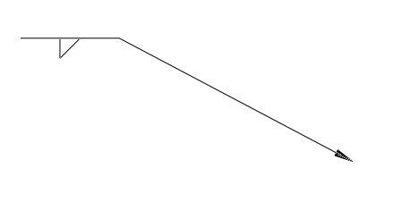
If the weld type symbol is above the arrow, then the bead will be laid opposite to the face the arrow is pointing towards, as shown below where the weld symbol points up, and a shaded area is on the opposite side of the arrow.
![]()
3 Types of Weld Symbols
Aside from adding the symbols above or below the arrow, there are three common types of welds you may use in your designs.
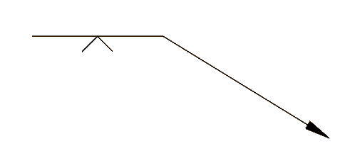
1. A triangle represents a fillet weld.
2. A V represents a V-groove weld.
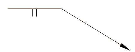
3. Two parallel lines represent a square weld.
What Do the Numbers Next to the Weld Symbol Mean?
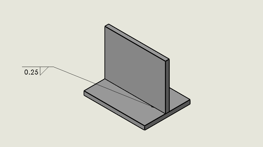
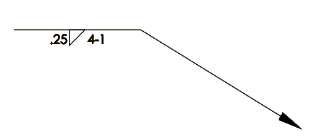
You may see numbers to the left and right of the weld type symbol. The numbers on the left represent the size of the weld, while the numbers to the right of the weld type symbol represent the length of the weld. If a dash follows the length, the number represents the distance between intermittent welds. Below, you can see a weld type symbol with 0.25 on the left and 4-1 on the right.
4 Easy Steps to Create Weld Symbols
Now it’s time to see how easy it is to access those weld type symbols inside SOLIDWORKS. SOLIDWORKS has the option of creating the complete symbol while the part is being created or after it has been put inside a drawing.
STEP 1
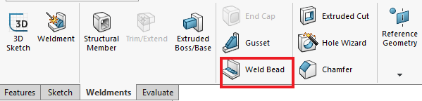
Let’s first look at weld symbol creation inside the part environment. Two quarter-inch plates will be welded together using a quarter-inch fillet weld. To create a weld bead, click on the Weldments tab on the CommandManager and click on Weld Bead.
STEP 2
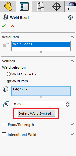
In the PropertyManager, we can define the weld by using Weld Geometry or Weld Path.
The Weld Geometry allows two faces to be chosen so a weld bead can be laid between them. Weld Path allows an edge to be selected where the weld bead will be placed.
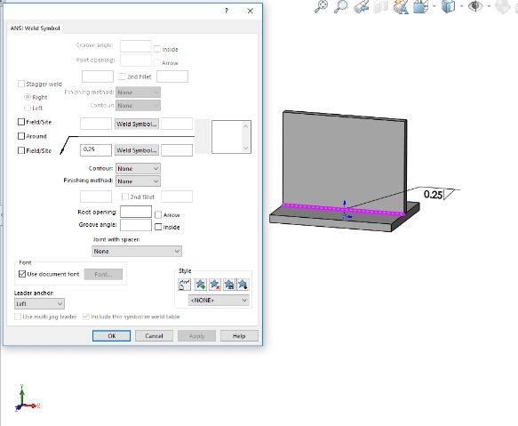
STEP 3
Once the location is defined, the Weld Symbol dialogue box appears. Here we can add the weld type, size, and direction information.
STEP 4
After finishing in the Weld Symbol dialogue window and completing the Weld Bead feature, the weld symbol will appear. After saving the part, weld symbols can be brought into drawing views by using Model Items on the Annotation tab.
Weld symbols can also be made directly in drawings. While in the drawing environment, the Weld Symbol tool can be found on the Annotation Tab.
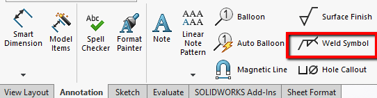
The same dialog box as found in the part environment is used to create the symbols. The weld symbol is placed by clicking on the desired location of the weld. The weld symbol is now finished and will be snapped into place.

The Final Note: Weld Symbols Streamline Design Processes
We covered the basics of the weld symbol tools and what some weld symbols mean. The ability to create weld symbols while in a part environment helps streamline the design process by having them transfer to corresponding drawing views.
SOLIDWORKS carries all the necessary weld symbols to ensure the welder on the floor understands what it is the designer wants.
If you have any questions or additional tips or tricks using the Weld Dialogue more effectively, contact us.


