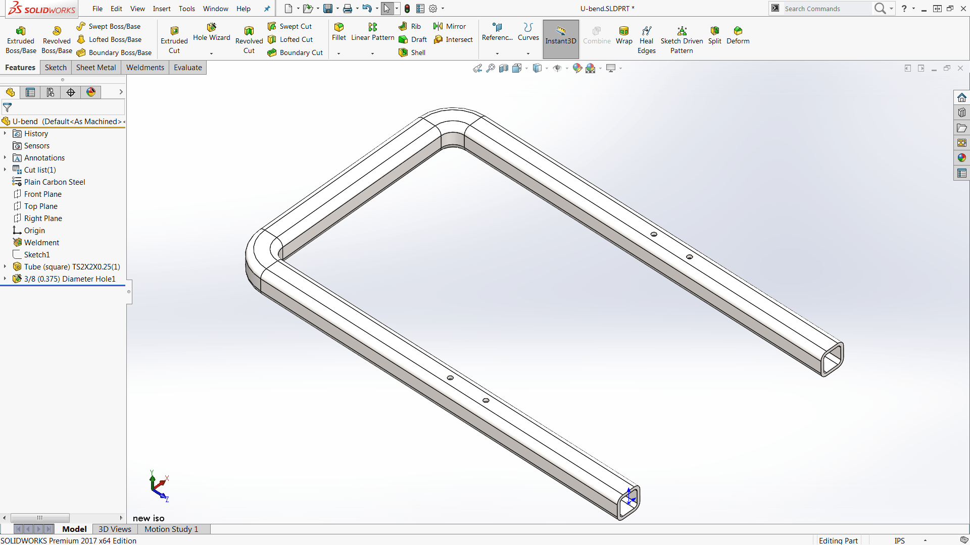
 A simple bent square tube with bends in a single plane. A simple bent square tube with bends in a single plane. |
This topic came from a recent customer question of how to get a flattened or unbent version for bent square pipes. Their goal was to get an unbent length to work with as well as locate holes along the tube. The easiest way to achieve this for both native SOLIDWORKS and imported parts is by using the Insert Bends Sheet Metal tool to flatten the major bends.
It should be noted that this article is Part 1 of a two-part series, and is geared toward “simple” bent tubes, or tubes that have bends only in one plane, as pictured above. For more complex cases (such as bends in multiple planes, as shown below), please refer to Part 2 in the series (coming soon). However, please begin by reviewing this article, as it covers important pre and post-processing techniques that will be leveraged in Part 2.
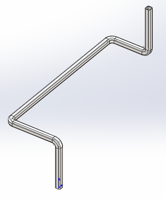 Multi-plane bends like this are covered in Part 2. Multi-plane bends like this are covered in Part 2. |
Disclaimer: the calculations made by SOLIDWORKS to determine the material stretch, or bend allowance, are specific to sheet metal designs, and may not be accurate for hollow pipe/tube. While this method will give you a better approximation of the unbent length when compared to the bent centerline length (the sketch that would be used for a Weldments part), consider creating test parts to determine an appropriate bend allowance value for the most accurate results.
Before converting the design into a Sheet Metal part, some pre-processing steps are required. The first step is to remove all of the extra rounded faces of the tube, as the Insert Bends command will consider these sheet metal bends. Additionally, any end cuts on the pipe must be removed/suppressed, as these will result in a shortened pipe once flattened.
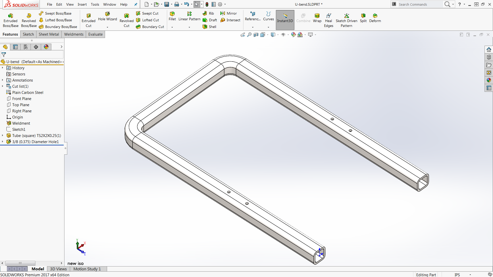
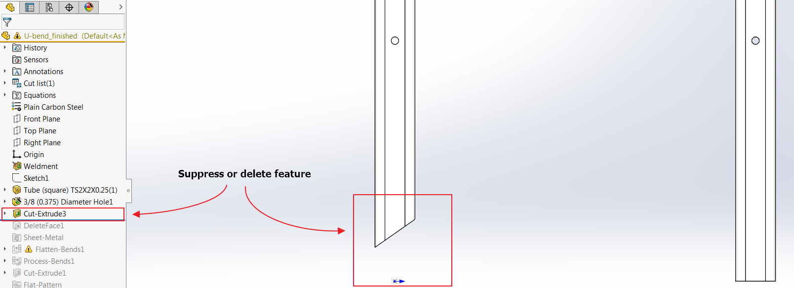 Suppress or delete features like end holes before converting to sheet metal. Suppress or delete features like end holes before converting to sheet metal. |
To remove excess curved faces, Power Select can be used to quickly select all of the faces, and the Delete Face command can be used to remove them. Open Power Select from the Select drop-down menu.
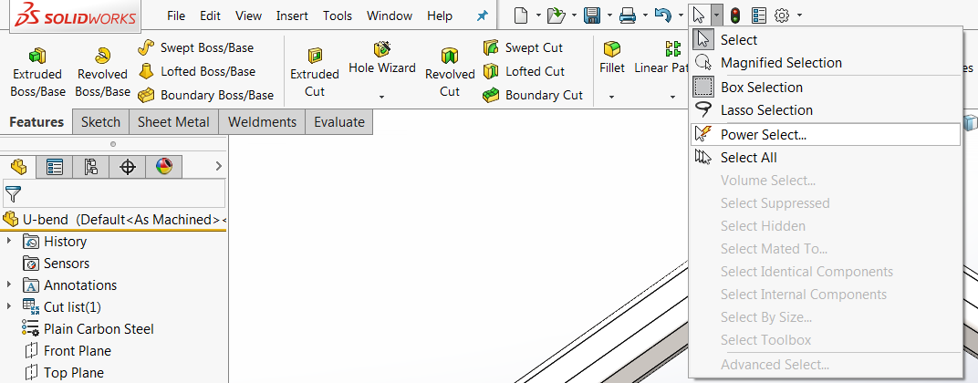 Open Power Select from the Select drop-down menu. Open Power Select from the Select drop-down menu. |
Select Faces under the Select What section. In the Filters and Parameters box, scroll to the very bottom and select Surface type. Select Cylinder, Cone, and Torus. Click New Search to find and select all faces that meet this criteria, then click Close. This will retain the selection.
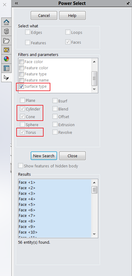 Filter by Cylinder, Cone, and Torus surface types to grab every curved face at once. Filter by Cylinder, Cone, and Torus surface types to grab every curved face at once. |
Now begin the Delete Face command. This can be found in the Right-click menu under Faces, the Direct Editing or Surfaces CommandManager tabs, or Insert > Face > Delete Face.
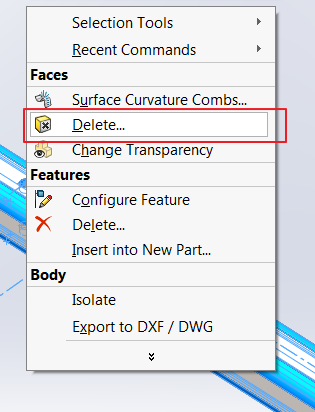 Start Delete Face from the right-click Faces menu. Start Delete Face from the right-click Faces menu. |
Once in the PropertyManager,all inner faces of the tube must be selected. To do this, right-click on an interior face of the tube and click Select Tangency.
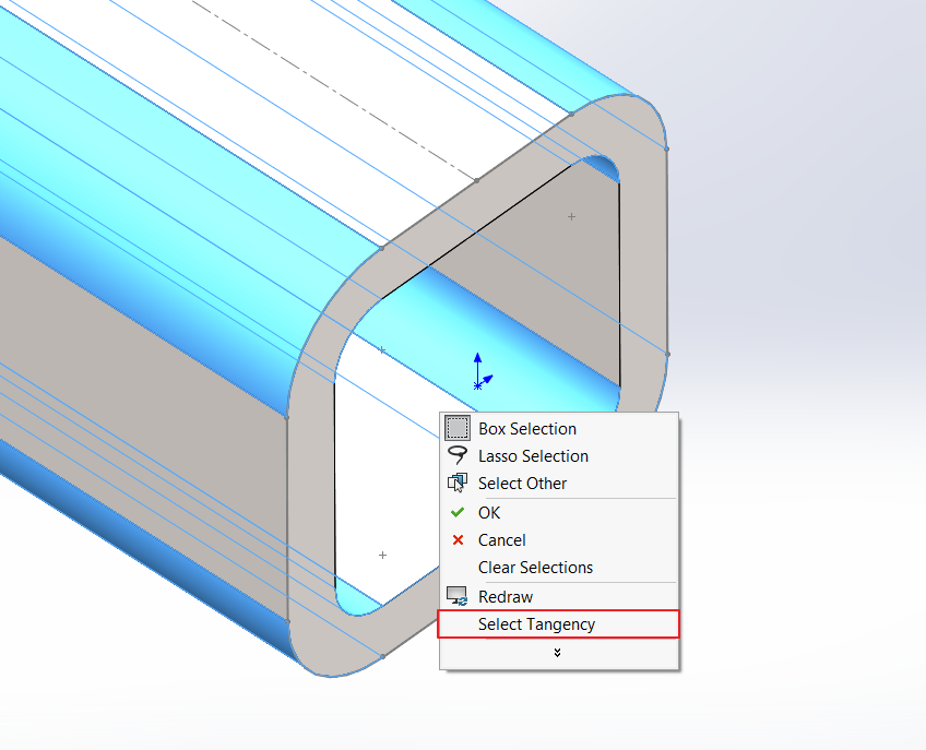 Right-click an inner face and choose Select Tangency to grab all interior faces. Right-click an inner face and choose Select Tangency to grab all interior faces. |
The Power Select command will select a few too many faces and the faces of the bends to be flattened must be deselected by clicking on both the inner and outer faces of the bend. Finally, select Delete and Patch.
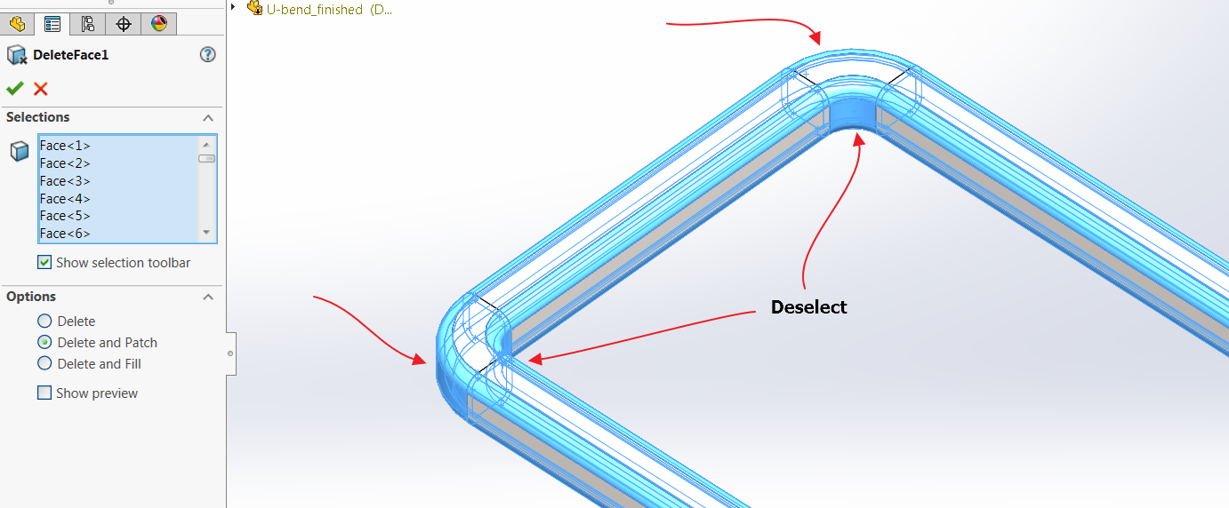 Deselect the inner and outer faces of each bend, then use Delete and Patch. Deselect the inner and outer faces of each bend, then use Delete and Patch. |
At this point,the Insert Bends tool can be used, and is found in the Sheet Metal tab of the CommandManager. Start up Insert Bends and select a flat face that is along the same set of faces as the bends that are to be flattened. Click Okay, and the process will be complete.
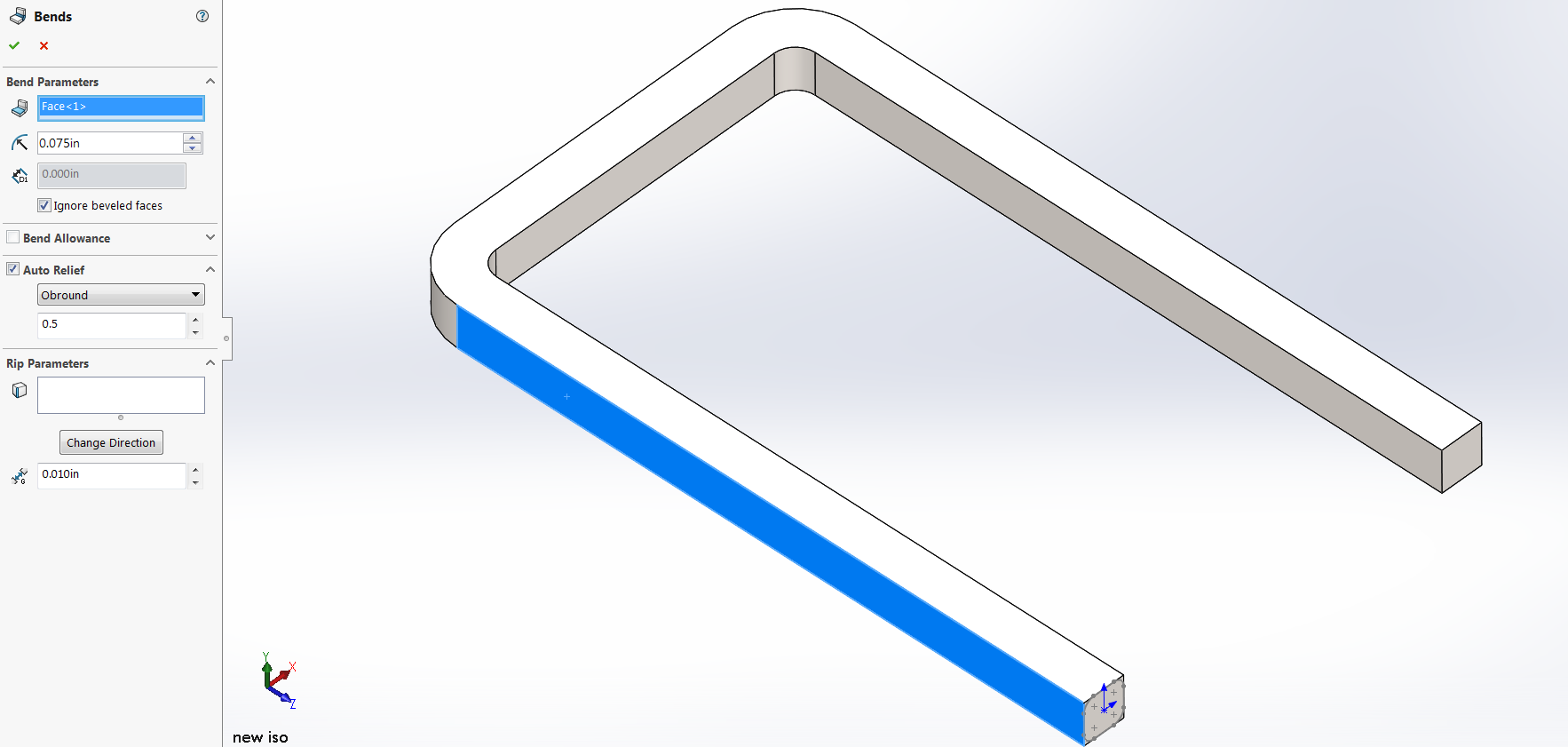 Insert Bends converts the tube to sheet metal using a flat face as the fixed reference. Insert Bends converts the tube to sheet metal using a flat face as the fixed reference. |
If there are any features on the bent tube that need to be included, such as holes or end cuts, it should be noted that the conversion to sheet metal will remove these. After the Insert Bends tool has been used, these features can be recreated by reusing the sketches, reordering the FeatureManager Design Tree, or by using the Convert Entities command (especially helpful for imported parts).
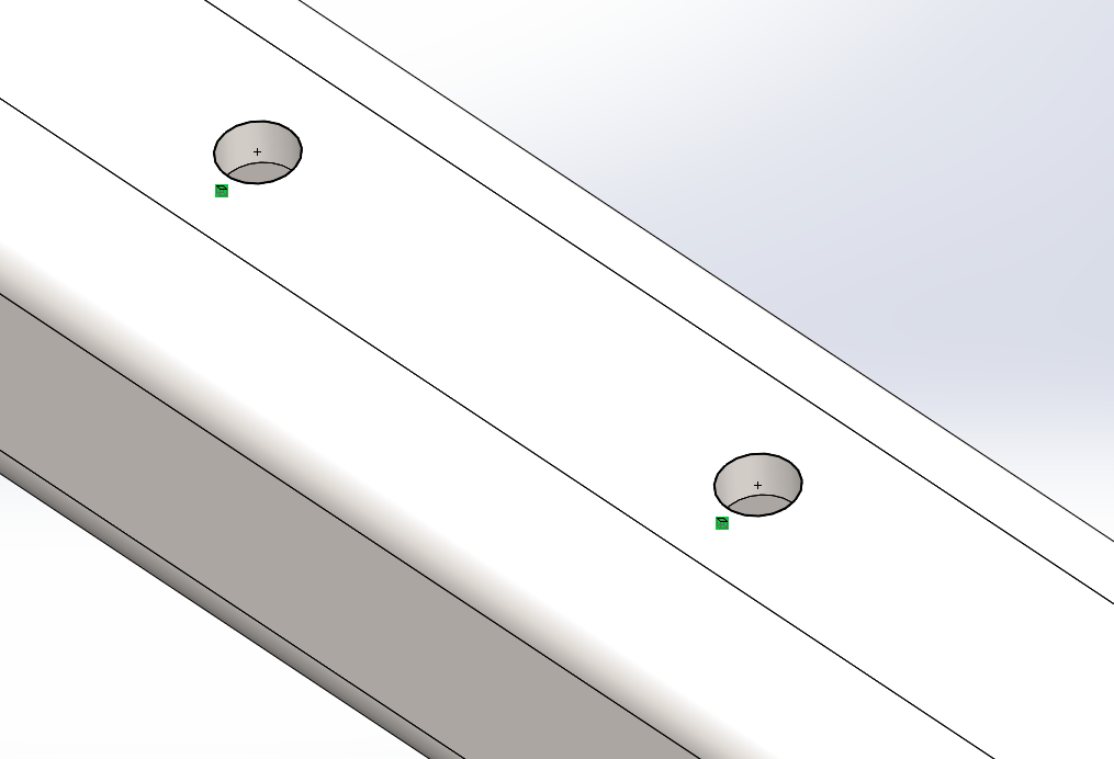 Holes and end cuts are recreated after the conversion. Holes and end cuts are recreated after the conversion. |
You may also notice that the end result does not share the same physical appearances as the original tubing. If this is important, Convert Entities or reuse of the original sketches (depending on how the bent tube was originally created) in conjunction with the Cut-Extrude command can be used to fix this.
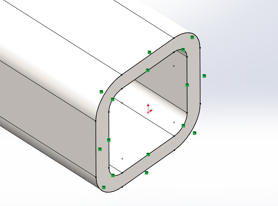 Reuse the original profile sketch to restore the tube’s appearance. Reuse the original profile sketch to restore the tube’s appearance. |
If using a profile like the one above, be sure to select the Flip side to cut option in the Cut-Extrude PropertyManager.
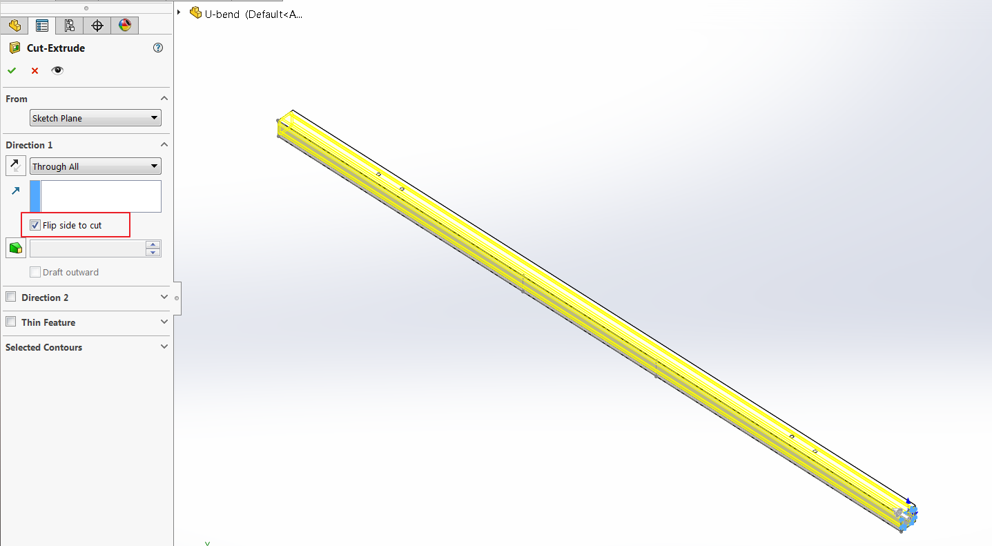 Check Flip side to cut when using the profile sketch on the flat pattern. Check Flip side to cut when using the profile sketch on the flat pattern. |
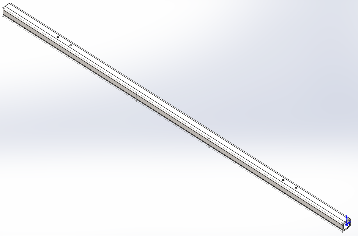 The flattened tube, ready to detail in a drawing. The flattened tube, ready to detail in a drawing. |
At this point you will have a part that is ready to be detailed out in a drawing, while still maintaining parametric control built into the part. Also keep in mind that if any new sections are added to the part the Delete Face feature will need to be updated. Remember to check out Part 2 in this series to see the extra techniques for dealing with more complex cases. For more information, check out our YouTube channel, get a SOLIDWORKS 3D CAD quote or contact us at Hawk Ridge Systems today. Thanks for reading!