 |
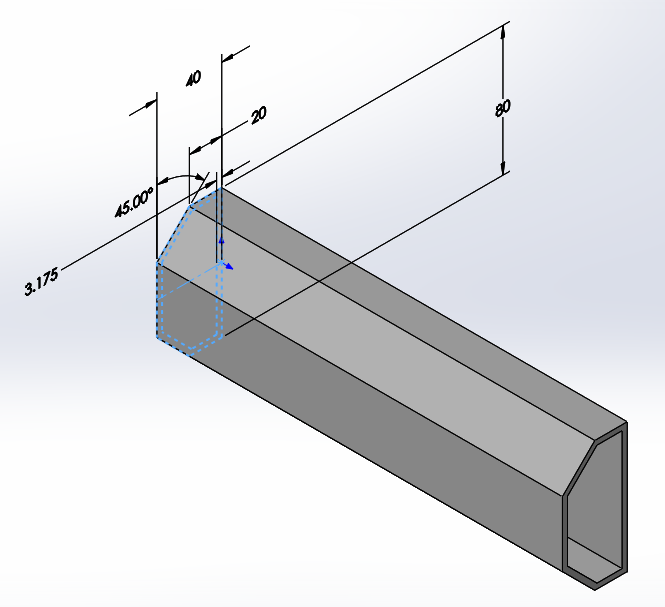
I’ll take that as a yes. To start with, let’s look at the part that I’m going to be using for my custom duct. I created the shape of the duct with a sketch and extruded it.
 |
Besides creating the sketch and extrusion, this part has custom names in it and we will need to do some work before this part is ready. Once the extrusion is created, you need to name it EW_EXTRUDE and name the sketch to EW_SKETCH. SOLIDWORKS needs these names to be in this format to recognize the information. I’ve also created a mate reference using the Electrical Component Wizard and an EW_PATH sketch so that wires route through the middle.
 |
Another configuration needs to be created in addition to the default configuration and named EW_CONFIG. Once that is done, let’s take a look at the dimensions of the sketch. The height and width dimensions have been renamed and we’ll keep track of these dimensions for a future step. The other thing I want to emphasize about these dimensions is that they’ve been set to the EW_CONFIG ONLY. This is very important, because if you don’t do this, you won’t be able to adjust the length of the duct in Electrical. When the length is adjusted, SOLIDWORKS Electrical creates new configurations for each length.
 |
 |
 |
The depth dimension has been renamed as well. Alright, enough preparation. It’s time to add this to my electrical project!
 |
Here is my fireplace with a harness in it, but I want to add in the custom duct down in the bottom for a future harness.
 |
The first thing I want to do is to add the duct to the location. To do that, right-click the L1 location in the Electrical Manager and access the Properties. If the part is already in the database, you can search for it, but mine isn’t and I will need to add it in manually by clicking Add manually.
 |
You will need to put in the Reference and the Manufacturer. I’ll put in CUSTOM DUCT and just select XYZ. I also like to put in the Class. Under Illustration, I’ll select the 3D part that I created. Here’s where the Width, Height, and Depth are important. In my case, they are 40, 80 and 250 respectively so I will put them in. These are minimums, so start small and adjust your part bigger. I will also check on the adjustable box so that the length field will update in these properties.
 |
Once I hit okay, the software asks if I want to add this to the SQL database. I’ll keep it Only for this component, but add it to the database if you want to reuse it.
 |
Now that it’s added into the Electrical Manager, I’ll right click on it and Insert it. Currently, we can’t insert it as a Duct or Rail, but we’ll still be able to adjust the length of it.
 |
Because I put the mate reference in the part, it picks up that mate reference on the bottom of the fireplace, and I’ll place that down and put it near the back.
 |
It’s not quite long enough, so I’ll hit the Change Length button and key in the new value of 380mm, about 15”.
 |
 |
You can see that my duct updates. Also, a new configuration is created in the 3D part to match the new length.
 |
I hope you enjoyed this article. For more information, check out our YouTube channel or contact us at Hawk Ridge Systems today. Thanks for reading!


