As the holiday season approached, Hawk Ridge Systems decided to host a design challenge for a 3D printed tree ornament. Everyone who submitted a design would receive their ornament after being printed on one of our 3D printers. All submissions were required to fit into a 2” cube bounding box and the eyelet geometry was provided to us.
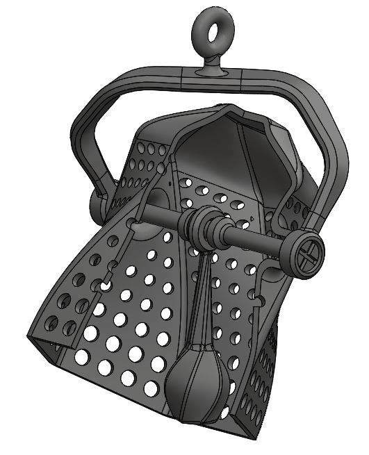
I wanted to create something that could only be manufactured by 3D printing. With this in mind, I knew I wanted complex undercuts or drafts that couldn’t be achieved by traditional molding. I also wanted it to incorporate an as-printed assembly. You can see the end result below!

This blog and the companion YouTube video details some of the key design steps and thought process I took during the design. A second blog and video covers the design checks, rendering output, and the finished 3D print.
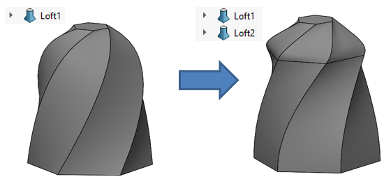
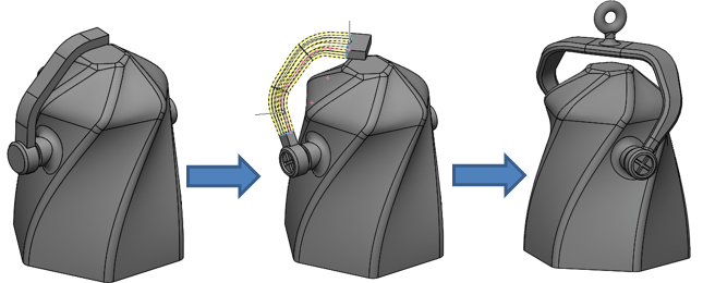
I liked the idea of an actuating bell and decided to start off with an overall shape that was a twisted loft. When generating the shape of the body I initially used the solid Loft feature through three polygons with a single feature and some twist, but I was unhappy with the result. Splitting up the loft into two features allowed me to create the more angular shape I desired, as you can see below.
Midway through the design, I decided I was unhappy with my boring straight concept for the mounting arm. Rather than deleting my features to that point and creating more re-work, I employed direct editing commands like Split, Move/Copy Body, and Move Face to essentially bend the arm into the shape I wanted.
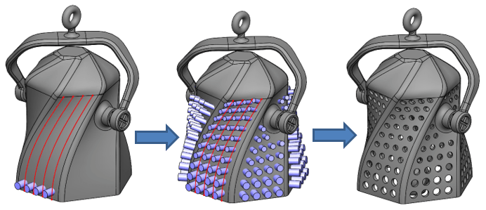
After adding more detail to the design I wanted another flair to showcase the 3D printed nature and wanted to add perforation to the exterior. Simple cylinders were extruded and then patterned along Face Curves with a curve driven pattern. I adjusted the size and position of the cylinders to my liking with the move/copy body command and move face command before subtracting them from the bell body to produce the final hole pattern. This gave me the control I wanted to get the look just right!
As far as manufacturability is concerned, this design features a wall thickness of 1 mm, with a minimum hole size of about 1 mm as well. In practice, we have found that with our 3D printers, we are able to print details and wall thicknesses even smaller! I modeled in 0.5mm of nominal clearance between the components to ensure ease of post-processing.
To see the finished 3D printed result, along with validation steps for the assembly and rendering output, check out Part 2 of this blog!
For more information, check out our YouTube channel, get a SOLIDWORKS 3D CAD quote or contact us at Hawk Ridge Systems today.