Hi everybody! Welcome to the third and final part in my 3 part series on a tool to add complex distortions to your solid or surface parts called the Deform tool. In the first part of this series, I introduced the tool and went through one of the ways to use it, the point method. In the second part, I went through the Curve to Curve method. If you haven’t read either of them yet, you can get to them by clicking on these links: Part One. Part Two.
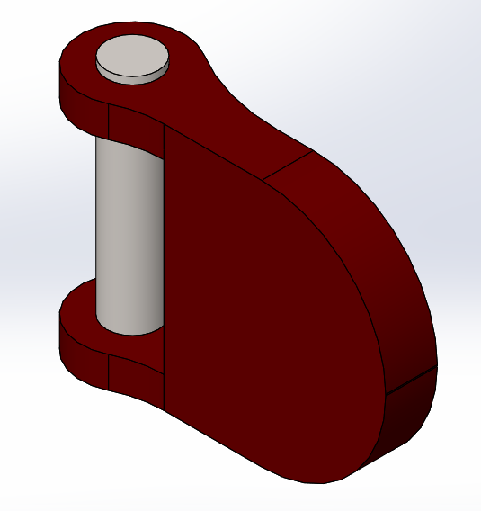
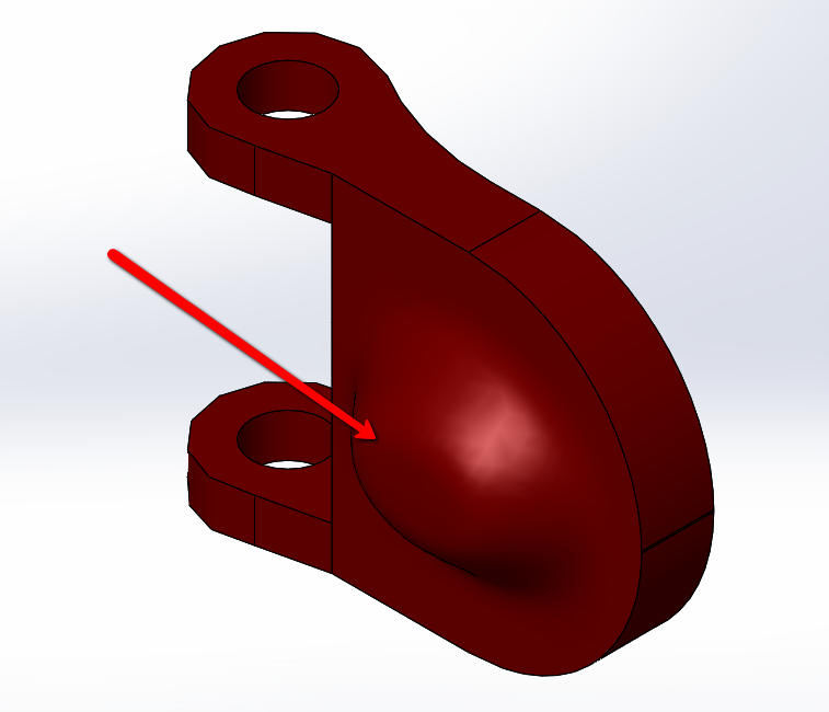
Let’s wrap this series up with the last way to use the deform tool, the Surface Push method. I’m using the same part from my other two articles, a gas cap.
 |
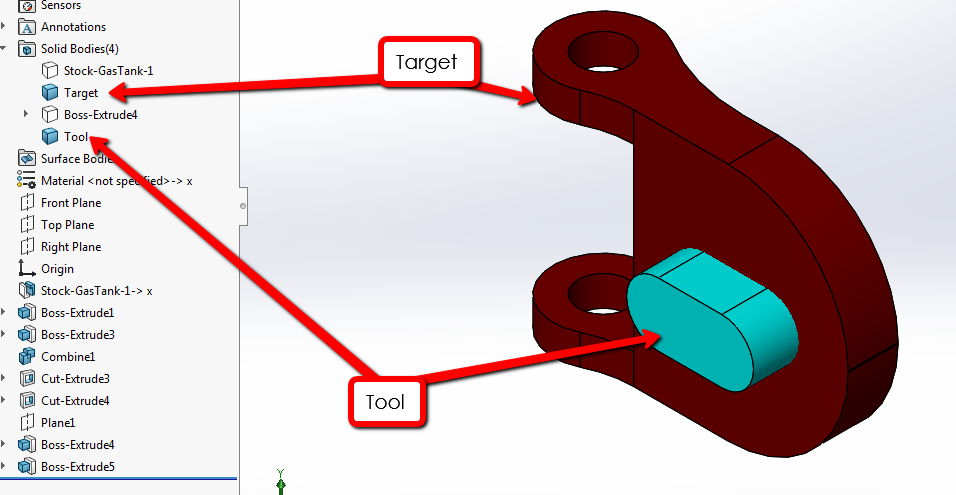
Before I start using the surface push method, I need a surface to deform up to, which is similar to the other two methods were I used a sketch. In this instance, I’m going to use a separate body. This is similar to other aspects in SOLIDWORKS, like swept cut, when you have a target and a tool body. You can select a pre-built tool body in the deform feature or create your own. I did the latter to get a specific shape and hid the pin for clarity.
|
|
I want to deform the top part of the cap to match the blue tool body. This body was created with a sketch that was extruded. We go back into the deform command (Insert->Features), and turn on the final option, surface push. The triad shows up at the Origin of the part, giving you the option of manually setting the Push direction or direction of deformation.
|
|
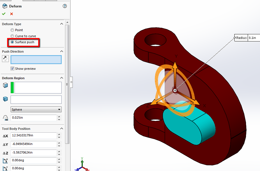
First I need to select a deform direction. In this case, it will be the Front plane and I’ll select that from the Flyout Feature Manager Tree. Think of this like a direction of pull if you are familiar with molds or draft analysis. In the Deform Region box, I select the faces to be deformed, which will be the front face of the cap. I will also specify the body to be deformed, which is the Target body so that it deforms just that body.
|
|
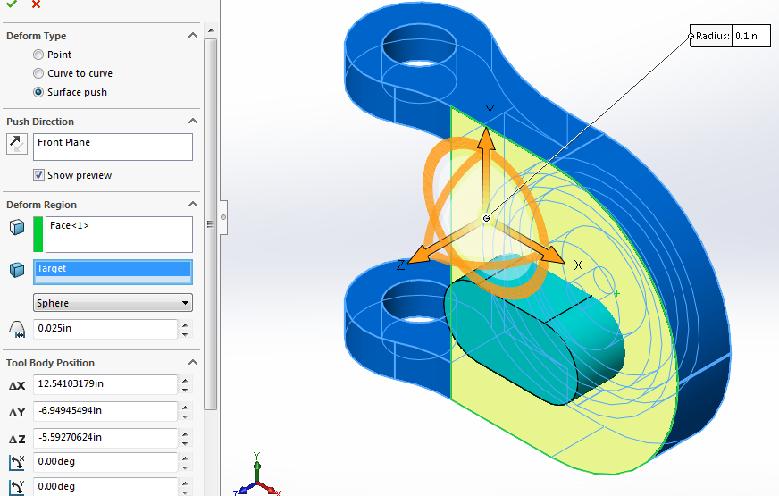
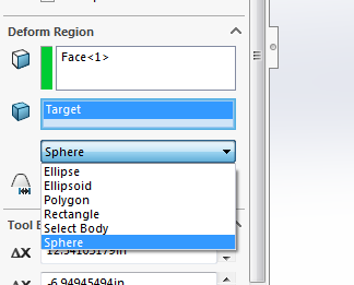
The last thing I need to select in the Deform Region box is the tool body. From the pull-down, we have some shapes to pick from. However, in this case, I created a custom body, so I’m going to use the Select Body option and select that blue tool body. The triad snaps to the body and I can adjust how I want the surface to deform manually using that.
 |
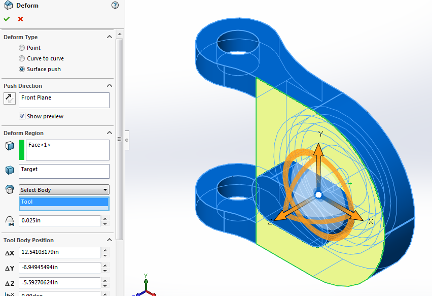
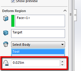
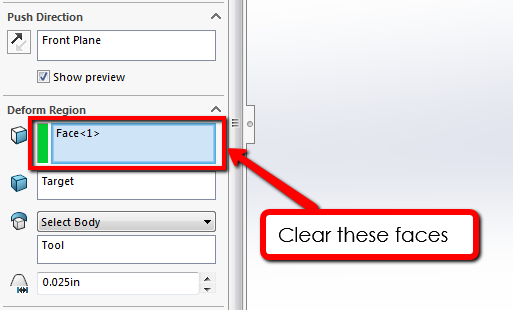
The last part of the Deform Region the deform deviation. If the value is smaller, the deformed body changes more. The preview is helpful in seeing this. I’ll make this 0.025 inches.
|
|
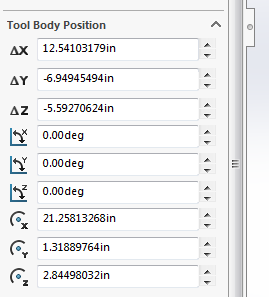
I’m not going to adjust any of these tool body positions translations because I want the new surface to match that tool body. Think of these as Move/Copy Body command if you would like to use these on your part.
 |
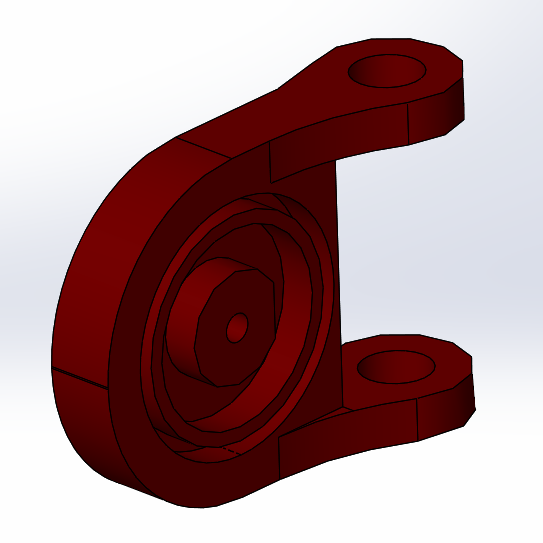
Hit okay and hide the tool body, and you see how the surface deformed in the tool body region.
|
|
If I flip around to the back, you can see that it’s flat, meaning that no other material was displaced except for the front faces.
|
|
I’ll go back into the feature and clear the selection for the face in the deform region so that just the body is selected.
|
|
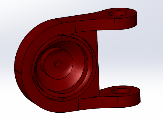
The top surface looks the same, but when I flip around to the back, we can see that the entire body deformed instead of just the front 2 faces.
|
|
That does it for this article and this series. I hope you enjoyed learning how to use Deform so that you can incorporate it into your designs. For more information or tutorials, check out our YouTube channel or contact Hawk Ridge Systems today. Thanks for reading!


