Hi, everybody! Welcome to the second part in my 3 part series on a tool to add complex distortions to your solid or surface parts called the Deform tool. In the first part of this series, I introduced the tool and went through one of the ways to use it, the point method. If you haven’t read it yet, you can get to it by clicking on this link.
Let’s go into the second method, which is the curve to curve method. I’m going to use the same part than I did in the first example, but I’m going to change the face that I will deform.
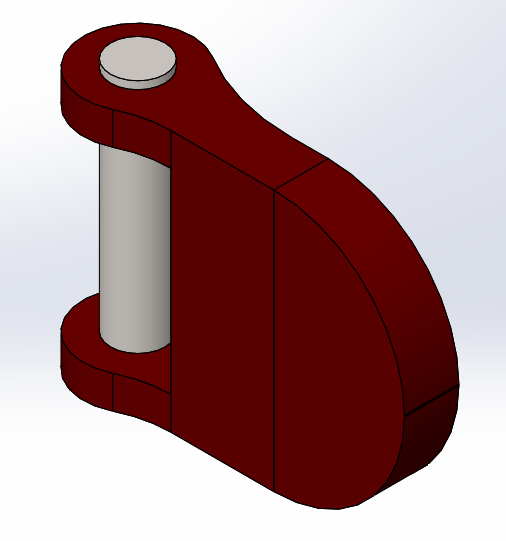 |
I already have a sketch here that is a spline to make the outside surface a more organic shape. Also, the top face has been split into 2 surfaces using a split line, I’ll come back to this a little later.
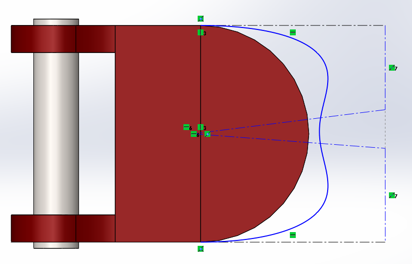 A spline sketch defines the more organic outside curve the top surface will deform to. A spline sketch defines the more organic outside curve the top surface will deform to. |
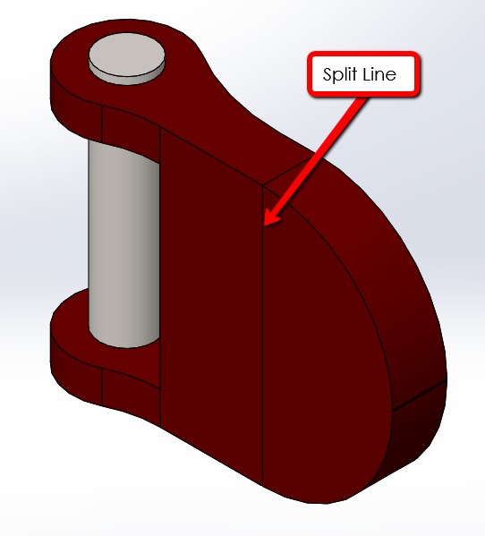 A split line divides the top face so only half of it will deform to the spline. A split line divides the top face so only half of it will deform to the spline. |
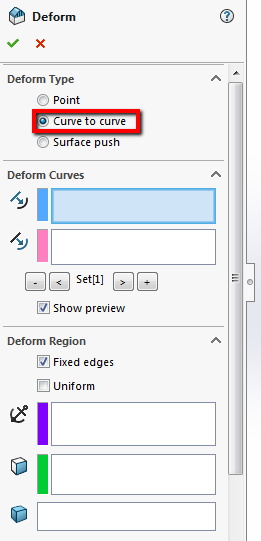
I need to go back into the deform tool. If you recently used this command, you can right click in the graphics area to access your recent commands. If this is the first time you are using it, it’s found under the Insert->Features menu. I’m going to specify the Deform Type as Curve to curve.
 |
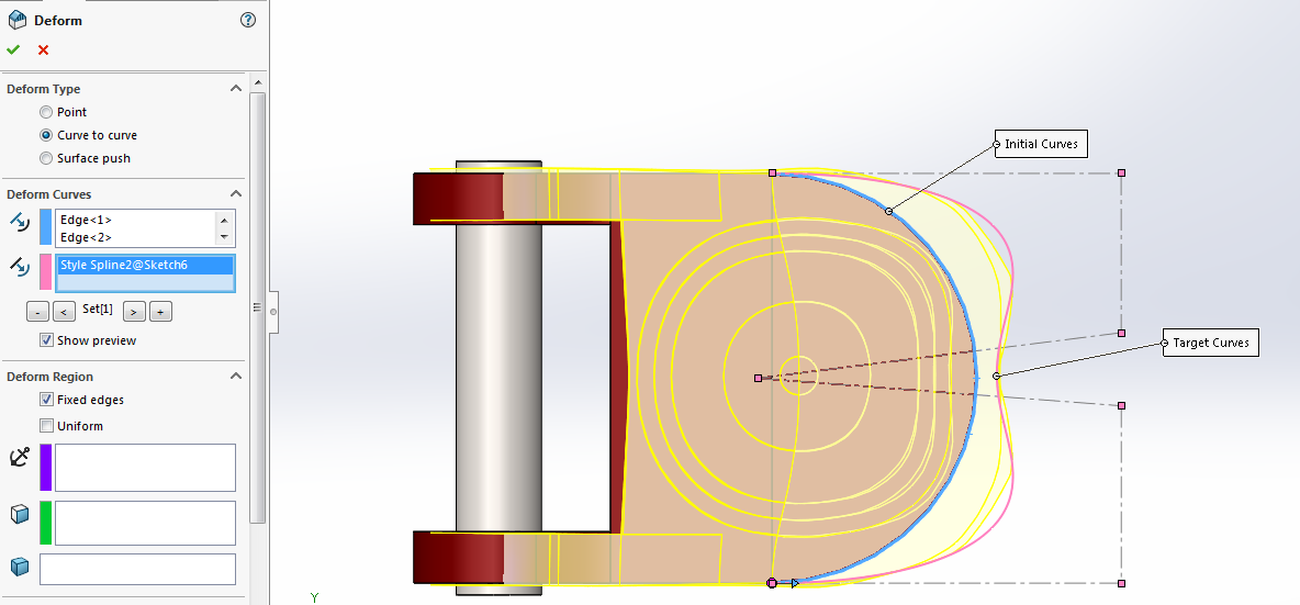
Under the Deform Curves box, I have some selections to make. The first is the initial curve, or what I want to move. That’s going to be the edge of the model. Next is the target curves, which is where I want that curve to move to. That will be that spline sketch. Once I select that, as you can see the whole model starts deforming. You can also select multiple sets of curves to have the shape deform in multiple directions. The material opposite of the edge being moved is compensating for the deformation.
 |
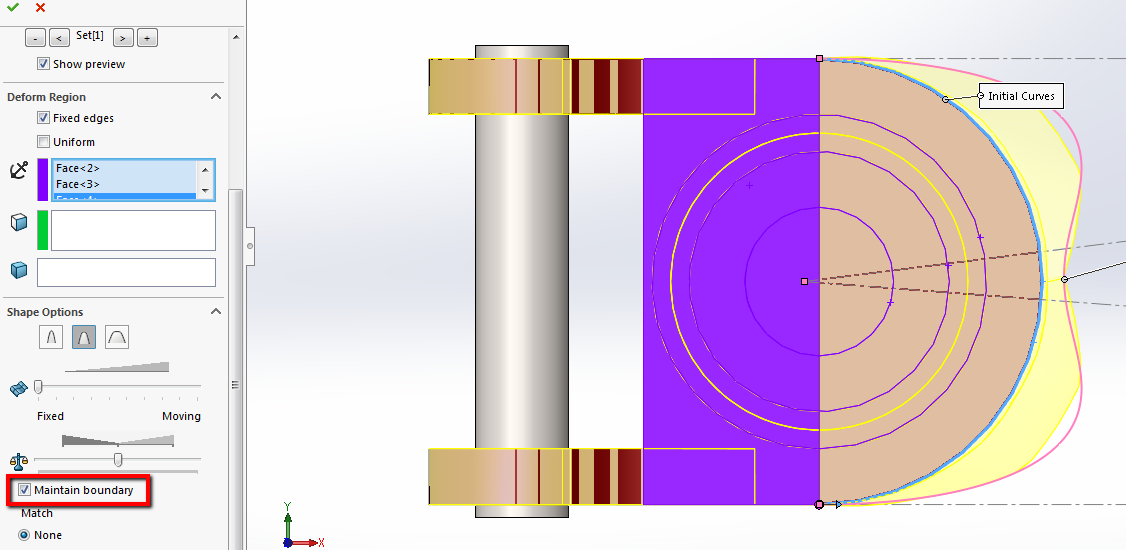
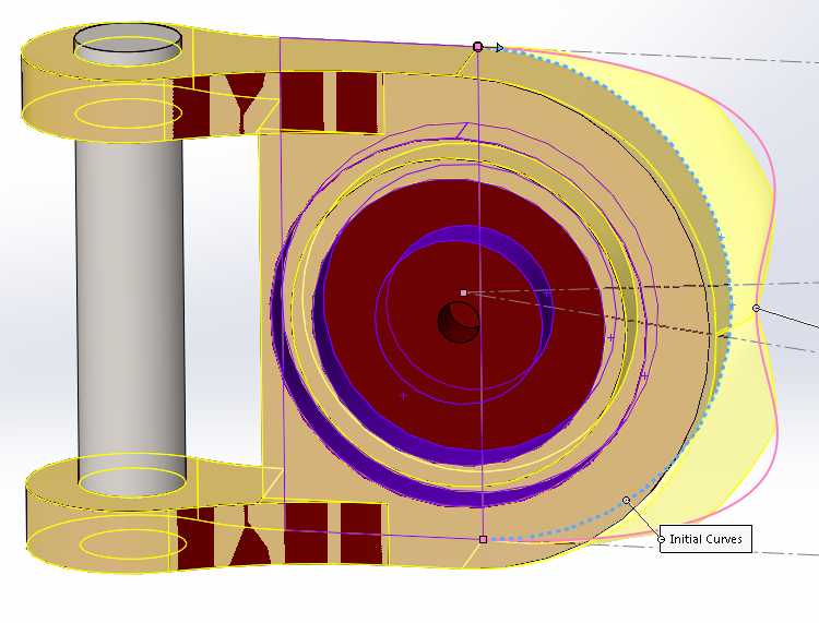
However, I split the face so that only the half closest to the edge will deform, so I will select the other face in the Deform Region as the fixed face so that it doesn’t change. I will also add some additional faces on the bottom so that the functionality of the gas cap is preserved.
 |
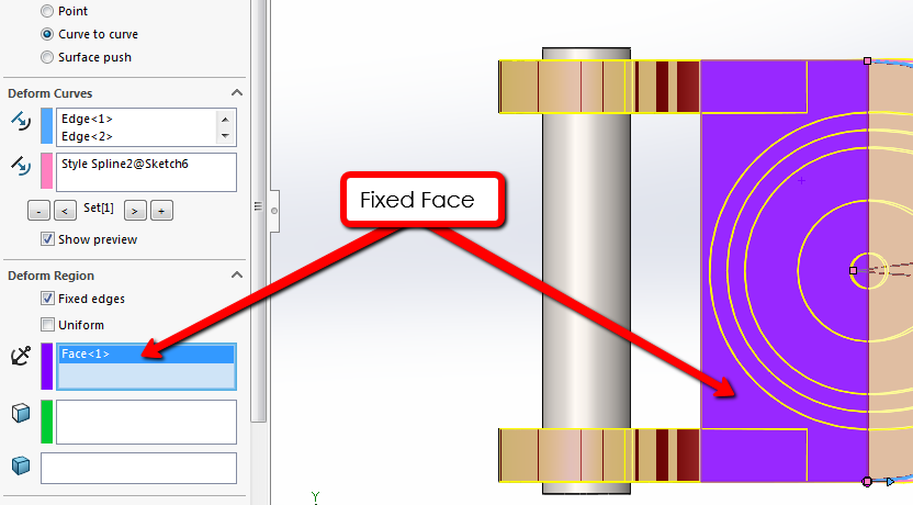 Selecting the other split face as fixed keeps that portion of the cap unchanged. Selecting the other split face as fixed keeps that portion of the cap unchanged. |
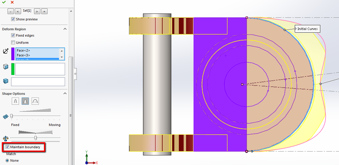
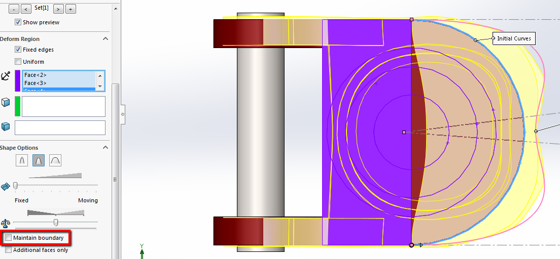
Similar to the point method, I can change the shape of the deformation by adjusting the stiffness in the Shape Options. If I toggle Maintain boundary on and off, you can see how the material will move along with the deformation if we don’t have it checked on.
 |
 |
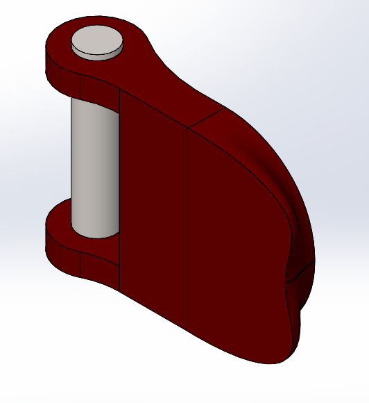
I’m going to keep the boundary on and hit okay. The cap has a much more interesting shape, which can be changed by adjusting the sketch with the spline in it.
 |
That does it for this article. In the next and final blog, I’ll cover the final deform method, so please stay tuned for that one. The next article will be on curve to curve option. For more information, check out our YouTube channel, get a quote for SOLIDWORKS Composer or contact Hawk Ridge Systems today. Thanks for reading!