 Introduction
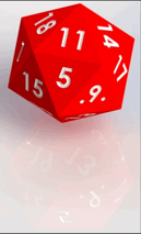
Have you ever prayed for a specific number while rolling dice? I know I have. With lots of role-playing games using dice of various shapes and sizes, I decided it would be fun to model some dice and see if I can manipulate the center of mass to roll the specific number I desired. I chose a D20 because it has a unique shape and is used very frequently in D&D.
Build
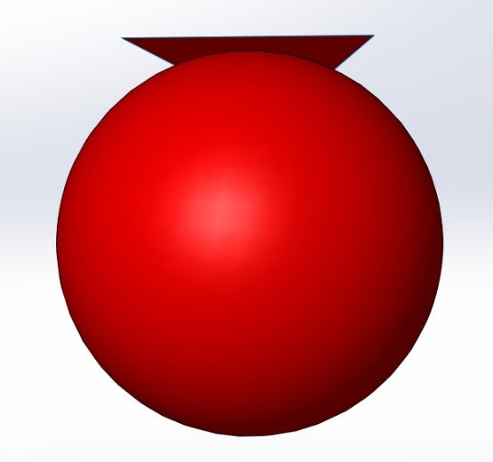
The shape I need to build is an icosahedron, it has 20 faces which are all equilateral triangles. To build my 20 sided die I used an equation and some surfacing techniques. The equation relates the length of an edge to the radius of an inscribed sphere that touches every face. I set a global variable to be the length of an edge and simplified the equation to ri = 0.7557613141 * length. Once I had my radius I did a simple revolve to create the inscribed sphere. I then had to create a plane for every face but to start I made the first plane parallel with the front plane and tangent to the sphere.
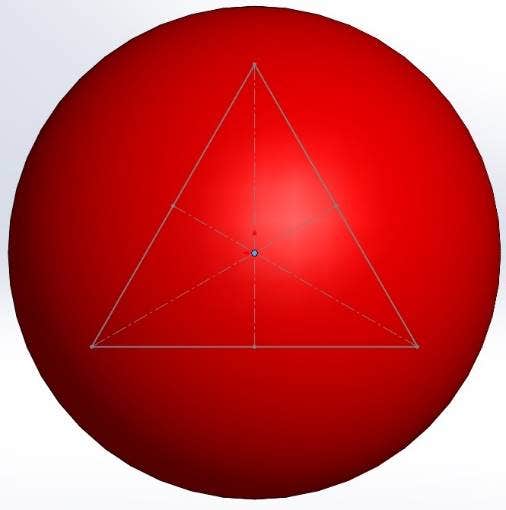 I then sketched an equilateral triangle on the plane and made the side lengths equal to the global variable. I made some construction lines to locate the center of the sketch so I can line it up with the origin. I saved this sketch as a block and made that center point the insertion point to expedite the rest of the design process. I created a Planar Surface with the sketch and that became the first face of the die. The next reference plane was created by being tangent to the sphere and coincident with one of the triangles edges. I then inserted the block and positioned one edge to be coincident with the previous triangle and the center to be located on the origin.
This process was repeated a total of 20 time when the final shape became apparent. After that Delete/Keep Body was used to remove the inner sphere and knit surface with the create solid option checked on converted all the surfaces into a single solid body. Finally some fillets and extruded cuts finished off the design by rounding the corners and numbering the faces.
Moving Center of Mass
In order to have the die land on 20, the highest number, I decided to move the center of mass of the part toward the 1 face. The one face happens to be the bottom when the 20 face is being shown. The first step I took was to hollow out the inside. I did this by using the Thicken feature but first I had to change the create solid option within the knit surface feature. This gave me a perfectly hollow die but then I had to add mass to the bottom. To start I created a plane that was parallel to the top plane with an offset which caused it to lay inside the die. The offset dimension is going to be the variable I am going to manipulate in a Design Study in order to optimize the location of the center of mass.
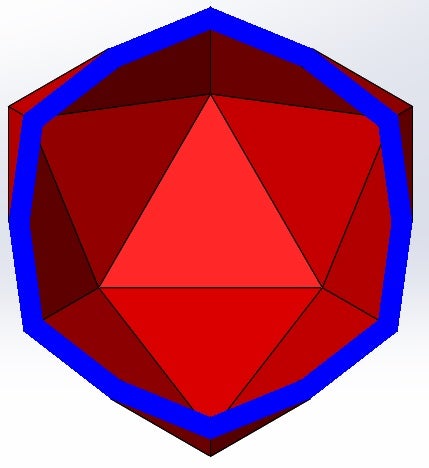
On this new Reference Plane I created a sketch with a simple line so I could make a rib. I choose the rib tool because it will automatically expand to the edge of the die which will capture my design intent no matter where the plane is placed.
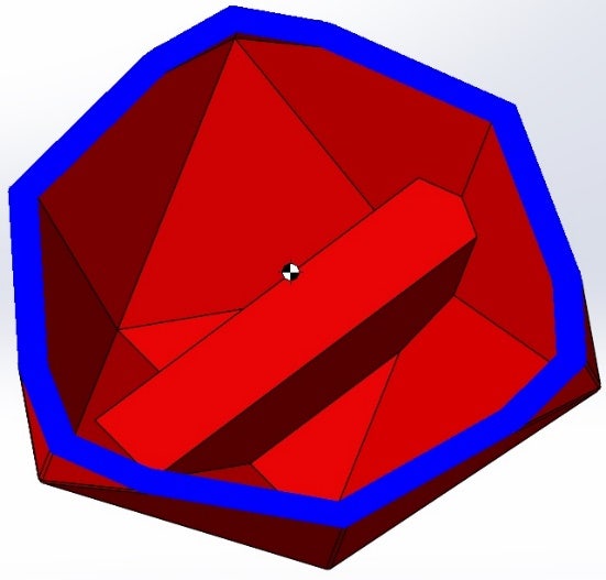
I then extruded the face of the rib with an up to body condition to fill in the rest of the vacant space. The convert entities command ensures that the geometry of the extrusion will match the rib as the plane height is manipulated by the design study.
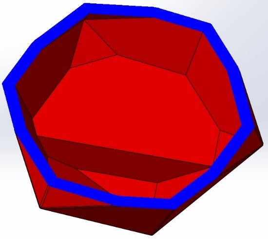
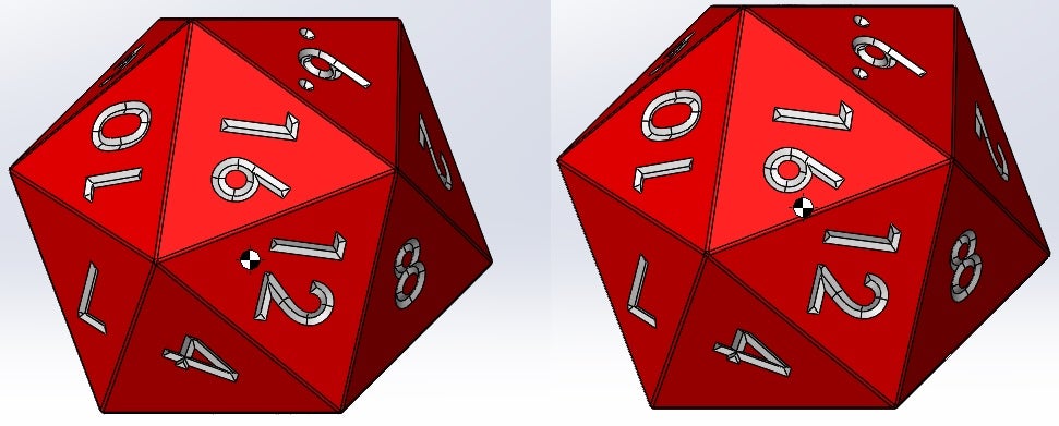
The Goal of the Design Study was to minimize the distance between the center of mass and the face with the number 1 on it. I created a measurement Sensor, between the center of mass and face 1, and used that in the design study. The study ran the variable through a determined range and calculated the sensor distance at every step. The optimized plane offset to minimize the distance between the center of mass and the number 1 face was 0.44 in. With the center of mass now where I want it, it is time to begin to simulation some rolls.
Simulating
The Motion Study will involve the weighted die and the solid die to act as a control. The first condition added to the simulation was gravity and that was easy to do in the motion tools, just a few straight forward clicks to define the acceleration and direction. A contact set was added between the dice and table resulting in a total of 3 contact pairs. The material of the dice and table were assumed acrylic for contact purposes with the default coefficients of friction and restitution. Since I am 3D printing the dice there is no information for me to find theses mechanical properties so this assumption will have to do until I can get some empirical data. A force has been added to one face of each die for a tenth of a second to give it some spin to better simulate rolling. The results of each die is displayed in the table below beside an animation of one of the simulations. The blue die is the weighted die and the red die is solid.
| Force (lbf) | Weighted Die | Solid Die |
| 0.035 | 17 | 15 |
| 0.039 | 20 | 1 |
| 0.04 | 20 | 5 |
| 0.041 | 20 | 7 |
| 0.043 | 20 | 12 |
| 0.045 | 20 | 3 |
| 0.055 | 20 | 16 |
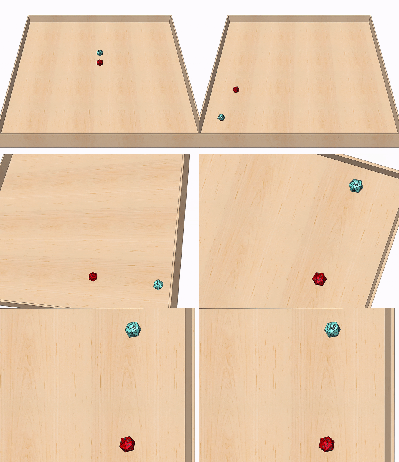
As you can see according to SolidWorks Motion and the information I provided it with the loaded die should be very effective. I can’t wait to print these parts and test them out in reality.
That concludes this article on SolidWorks: Controlling The Roll. There are a myriad of other new features and enhancements not covered in this article which we will detail in later posts. Be sure to check out our Webinar Wednesdays, and keep an eye on this page for new articles on our ever expanding capabilities; SolidWorks, SolidWorks Electrical, Enterprise PDM, SolidWorks Composer, SolidWorks Plastics, SolidWorks Simulation and CAMWorks.
For more information, check out our YouTube Channel, get a SOLIDWORKS 3D CAD quote or contact us today. Thanks for reading!
