Utilizing SOLIDWORKS Reference Geometry for Complex Designs
For basic SOLIDWORKS models, users can often complete designs by leveraging only the default planes and available model geometry. However, as the complexity of designs increases, it often becomes necessary to create and utilize reference geometry to produce models with appropriate design intent. Reference geometry includes planes, axes, coordinate systems, reference points, the center of mass, and mate preferences. In this article, we’ll cover the basics of creating planes, axes, and coordinate systems to help you throughout your design process.
Fly Reel Design
In this example, a fly reel is being designed, and so far everything has been smooth sailing.
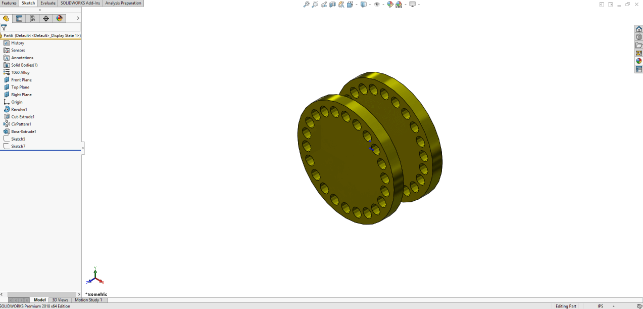
At this point, we want to create a rectangular cut on one of the larger cylindrical surfaces of the fly reel, but there is no flat surface to create a sketch. While offset options in the Extruded Cut command could be used to accomplish this, creating a plane tangent to the surface will be more robust, and will result in better design intent should the design be resized in the future.
Features Tab
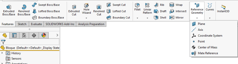
All types of reference geometry are considered features and can be found in the Features tab. To begin creating a plane, access the Features tab of the CommandManager, select Reference Geometry, and then click Plane.
New Planes
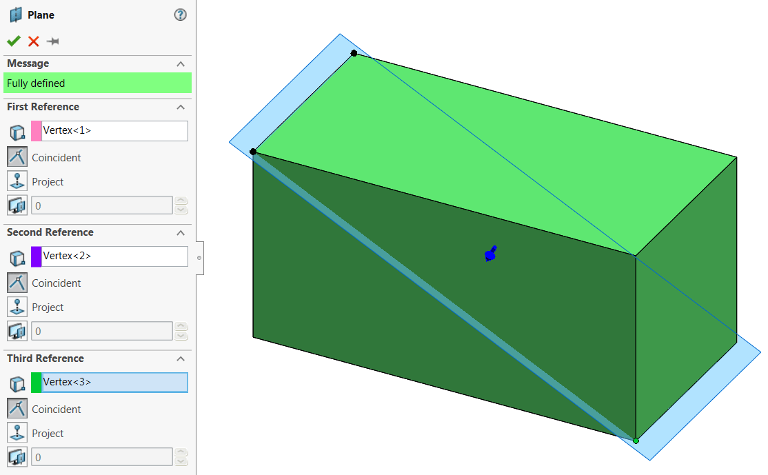
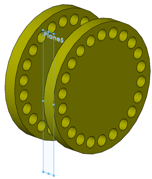
New planes are almost always defined by existing geometry, and there are several combinations of entities that can be used. Up to three references can be used to define the plane, with simple planes often requiring only one. Some common combinations include a single face, one edge, and one point/vertex, or three points/vertices. An example of a plane defined by three vertices is shown below:

FeatureManager Design Tree
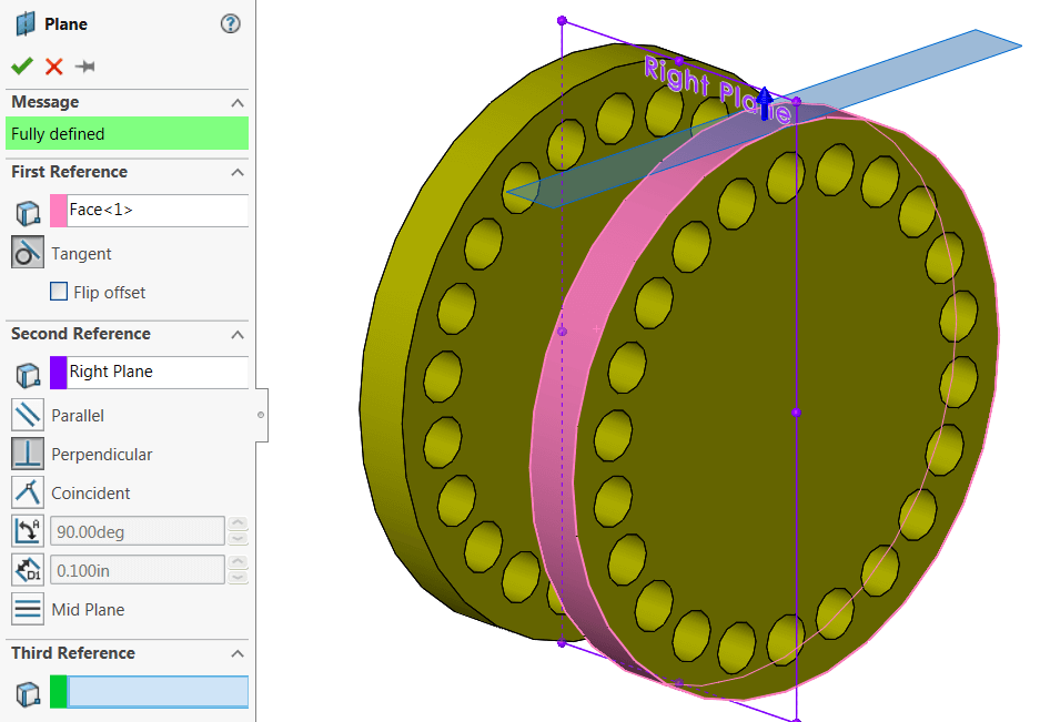
In our case, a plane is needed that is both tangents to the larger cylindrical face and parallel to the Right Plane. This requires the selection of two references. It should be noted that the order of reference selection is not important. Select one of the larger cylindrical faces, then select the right plane from the FeatureManager Design Tree. You may need to use the flyout FeatureManager to make plane selections if they are not visible in the graphics area. The preview of the plane should look as seen below:
PropertyManager
Notice in the PropertyManager that several options still exist to reorient the plane, even though the plane is fully defined. In some cases, planes may fail due to these options being set incorrectly, so we recommend trying a few of them before changing your reference selections.
In this case, set Second Reference orientation to parallel. This will change the orientation with respect to the Right Plane. If needed, the Flip Offset option in the First Reference box could be enabled to create the plane on the opposite side of the cylinder.
Once complete, the newly created plane should appear as seen below, and a new feature should be added to the Design Tree.
Newly Created Plane
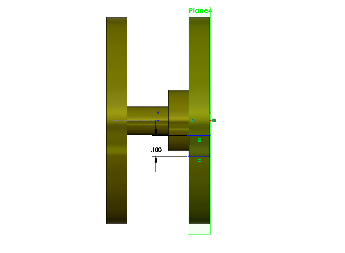
At this point, we are ready to add a sketch on the newly created plane. A simple rectangular sketch was created through the use of a corner rectangle, attached to the edges of the cylinder with a height of 0.1 inches. However, ensuring that it is properly centered on the reel is not particularly easy. This could be done with a combination of the midpoint and/or coincident relations, but depending on geometry, these may not be readily available.
Reference Axis
An alternative is to use a reference axis. Axes are commonly used for revolved features and circular patterns, especially when no convenient sketch entity or model edge exists for those features. In this case, we will use an axis to assist us in centering the sketch.
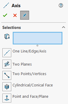
Fortunately, axes are significantly easier to fully define than planes, and the associated PropertyManager is fairly self-explanatory and is shown below.
It’s important to remember that in order to be used as a reference in sketches or features, axes (or any reference geometry, for that matter) must exist prior to creating the sketch or feature that references them. In this case, we’ve already completed most of the sketch, so to use an axis for centering, we would need to exit the sketch and use the rollback bar to create the axis higher in the Design Tree.
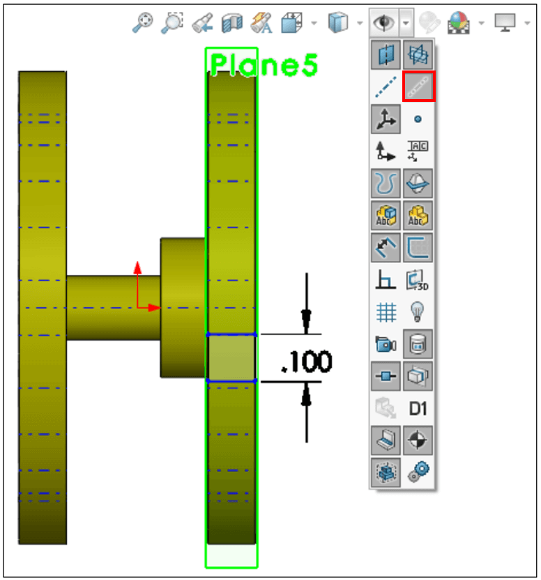
However, there is one more trick that can be used, specifically when working with cylindrical or conical geometry. Every cylindrical or conical feature is automatically created with what is known as a temporary axis, which follows a straight path through the center of the feature. To leverage these automatic axes, they must be made visible from the Hide/Show Items menu in the Heads-up View Toolbar:
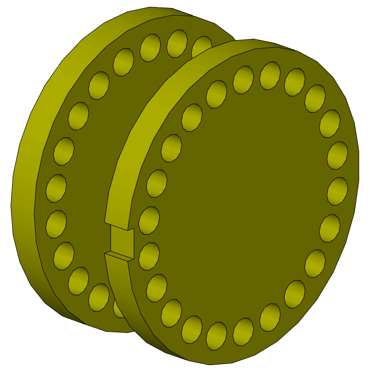
Once the temporary axes were revealed, the center axis was used in conjunction with one of the midpoints of either vertical sketch segment to create a coincident relation, centering the rectangle with respect to the connecting shaft. Finally, an Extruded Cut was created to produce the feature seen below:
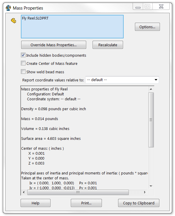
At this point, let’s suppose we need to determine the coordinates of the center of mass of the part. Luckily, SOLIDWORKS readily provides this information automatically in the Mass Properties dialog. Click on Mass Properties in the Evaluate tab of the CommandManager to see these results. Additionally, reference geometry for the center of mass location can be created from within this dialog, or from the Reference Geometry dropdown in the CommandManager.
While this information is helpful, it’s possible that you may run into a situation where the center of mass is needed with respect to another location (perhaps relative to mounting hardware) for downstream applications such as stress simulation. When this is the case, coordinate systems can be created and used to show this information. Coordinate systems can also be exceptionally useful for use with the Measure tool when exporting SOLIDWORKS parts to another format, or in facilitating assembly mates.
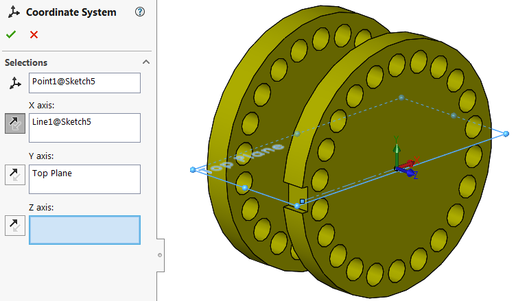
To show the center of mass relative to the mounting location of the fly reel, we’ve sketched a construction line on the large circular face from the center to the left quadrant in order to attach the coordinate system. From here, create a coordinate system by accessing Reference Geometry on the Features tab of the CommandManager and select Coordinate System. The first selection sets the origin, and as such should be the construction line endpoint at the center of the reel. The remaining selections set the orientation of the axes and can use linear or planar selections. It is not necessary to set every direction to fully define a coordinate system, and the reverse button may be used to flip the direction of an axis.
The resulting model and coordinate system can be seen below:
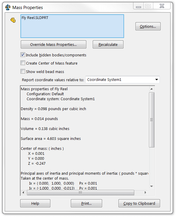
Finally, this coordinate system can be used to represent the center of mass coordinates relative to this location. Access Mass Properties once again, and this time, use the Report coordinate values relative to the dropdown window to select the new coordinate system. The center of mass coordinates will update to the appropriate values, as shown below (specifically in the Z direction). Your results may differ depending on the orientation of your coordinate system.
In this article, we covered the basics of using reference geometry in the context of designing a fly reel. Reference planes were added to facilitate an extruded cut on a non-planar face, and a temporary axis was used to align the rectangular sketch properly. Finally, a new coordinate system was created to determine the coordinates of the center of mass from a relative location.
Do you have any additional tips or tricks for using reference geometry more effectively? Let us know in the comments!
If you’re interested in getting more hands-on with SOLIDWORKS, register for Hawk Ridge Systems annual Design to Manufacturing Roadshow in a city near you! It will focus on What’s New in SOLIDWORKS 2019.


