SOLIDWORKS features a powerful set of Mold Tools for tackling complex mold designs, but it’s not always necessary to use them. If you’re just trying to make a simple cavity and mold split, you can easily accomplish this using the procedure outlined below.
Note: You can use a similar procedure with either a multi-body approach or an in-context assembly editing approach. For simplicity sake, we will cover the multi-body approach in this blog.
Getting Started
To get started, create a new SOLIDWORKS part file. We will insert our part that will be used to create the mold using the Insert Part command from the pull-down menus.
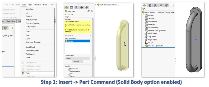
Make sure the “Solid bodies” option is checked and click the check mark. This will place the part aligned with the part origin.
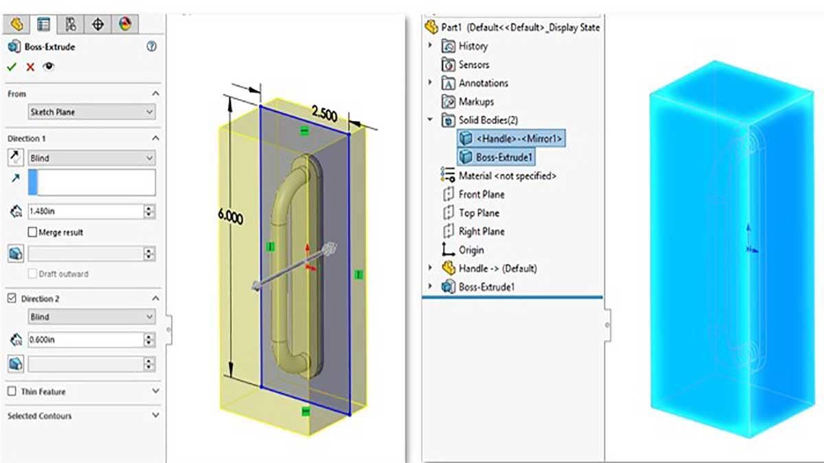
Next, create a sketch of the profile for the mold block. Create an Extrude feature to the desired depth, and be sure to clear the Merge Result option.
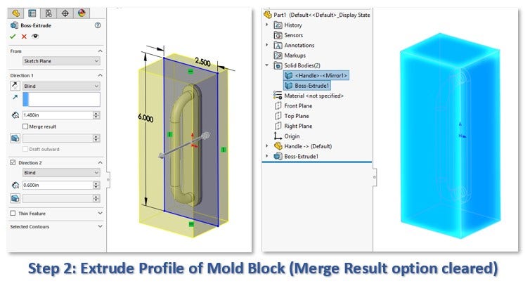
This will produce a second solid body to represent the mold, which should become visible from the Solid Bodies folder on the Feature Manager Design Tree, as pictured above.
Subtracting From the Mold
Next, we will subtract the original part from the mold.
Note: For a production mold, it may be desirable to insert a Scale feature to compensate for shrinkage. The draft angles of the part should also be analyzed and adjusted. These factors are not considered in this tutorial.
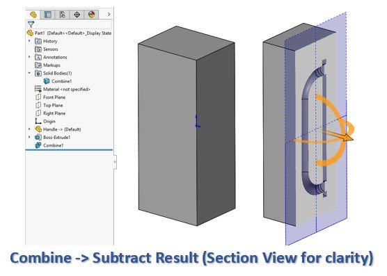
Insert a Combine feature by accessing the pull-down menus under Insert -> Features -> Combine. Choose the Subtract option and select the mold body as the Main Body, and the original part that was inserted as the Body to subtract.
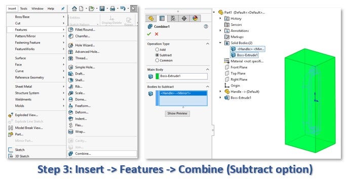
Click the check mark to proceed. The result should be as below – the part is now back down to a single body, and if you were to create a section view (optional) you would see that the cavity has been subtracted.
Performing the Tooling Split
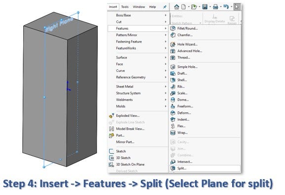
Now for the actual tooling split. This requires a Plane or Surface going down the parting line of the model. Check the Planes you have available and see if any of them satisfy this criteria. If not, create a new one using Reference Geometry -> Plane.
In this case, I will be using the Right Plane of my model, which runs down the middle, to split the mold block. Select the Right Plane and then insert the Split Feature from the pull-down menus, under Insert -> Feature -> Split.
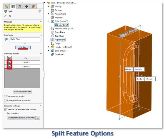
In the Split Feature, be sure the desired Plane is selected as the Trim Tool, then click Cut Part. Finally, check the check boxes underneath the scissors for the two bodies produced, then click the check mark.
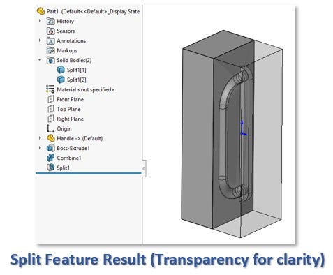
The Split Feature should result in two separate mold halves, as seen below. That’s all there is to it!
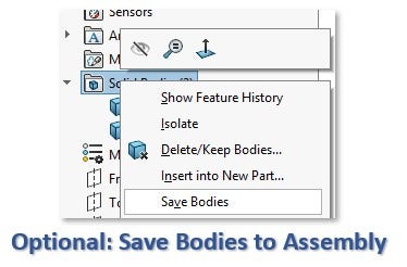
Since both halves exist as bodies within a single part file, it may be desirable to save them off as separate parts in an assembly. If you wish to do this optional step, Right Click on the Solid Bodies folder in the Feature Manager and choose the option “Save Bodies.” Be sure to check the check boxes for each body in the resulting prompt, and also choose the option to create assembly.
This should result in both bodies being saved out as separate part files, and placed into an assembly automatically.
It’s worth noting that the techniques described in this video can also be used for much more complex splits, such as the three way split pictured below.
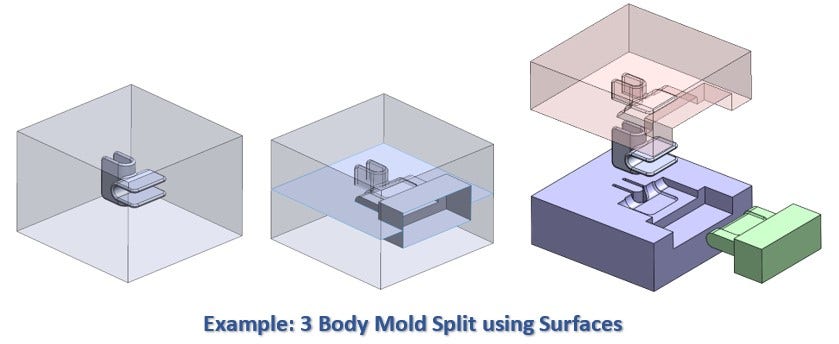
The only difference in this example is that instead of using a Plane as the trim tool for the Split feature, multiple surfaces were created in advance to be used as Trim tools.
For more information on SOLIDWORKS or if you have any questions, contact us at Hawk Ridge Systems today. Thanks for reading!


