Many users are unaware that the standard circular detail view sketch can be overridden with any other type of sketch geometry in order to capture only the desired information in a detail view. This article covers how to override the circular detail profile and ensure that the display matches appropriately.
Modifying the Border of a Detail View
SolidWorks users who frequently create drawings have undoubtedly used a detail view at one point or another, but many are unaware that the standard circular sketch used to define the border of a detail view can be overridden and replaced with any type of sketch geometry. This simple technique may be employed to exclude certain information from a detail view, or to conform to company standards.
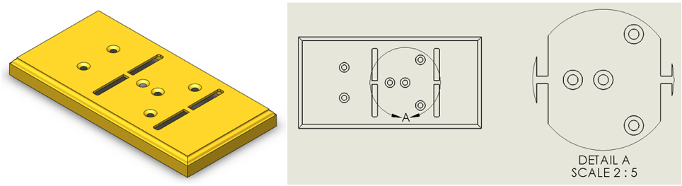
We’ll start off with a simple 3D model with a few holes and a couple slots, which we’ll use to generate a drawing. After dragging in a top view from the View Palette, we’d like to create a detail view that captures only the Hole Wizard features on the right-hand side of the part. However, the standard circular sketch that defines the border of the detail view includes some aspects of the slot features on either side of the holes, which we’d like to avoid.

Overriding the circular border for the detail view is very simple, as it’s driven by an underlying sketch. Simply right click the detail circle symbol (in the top view, in this case) and choose Edit Sketch. At this point, the circle will turn blue, and we’ve been placed in sketch mode, as indicated by the confirmation corner. All of the standard sketch tools are now available to us, and we can use whichever tools we’d like to create a new detail profile after deleting the circle. We’ll use a spline for this example, but any closed profile will work. After creating the new profile, use the confirmation corner to exit sketch mode and see the updated results.

At this point, you’ll find that the detail view itself appears to be updated, but the detail view symbol shown in the top view still appears as a circle. That’s because the style mode for the detail symbol is still set to “Per Standard” and will need to be adjusted to reflect the new spline profile. Simply click the detail symbol, and from the Property Manager, use the dropdown under Style to select one of the bottom three options. Additionally, change the radio button from Circle to Profile. This will force the detail symbol to reflect the new border profile.

Any closed contour can be used as a detail view profile, so you’re now free to create detail splines, rectangles, polygons, or any other shape you can imagine, allowing you to precisely capture the information needed in your detail views. Try it out, and let us know what you think. Happy modeling!


