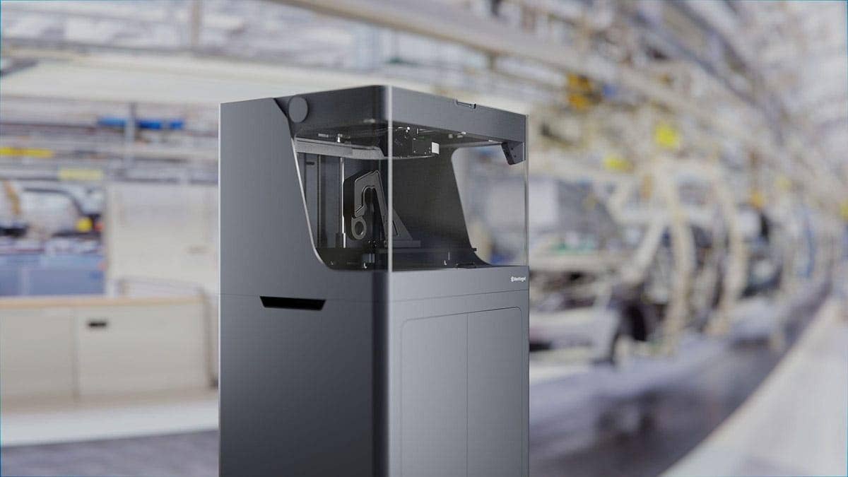
Earlier this year, Hawk Ridge Systems announced a partnership with Markforged, which is a 3D printing company that manufactures hardware capable of printing end use parts. In this first part of our content series, we will be covering the setup and configuration of our Mark Two, which is a printer that has the ability to inlay parts with continuous fiber filament. After the printer is set up, we will also be showing how a file can be prepared for printing in Eiger, which is the cloud based slicing software developed by Markforged.
In the second part of this series, we will walk through the design of a Markforged tool caddy, which was a project aimed at organizing many of the accessories that came with our printer. This project was our first major print, and after some of our design considerations are outlined, we will show the finished product!
Initial Setup
Firstly, if you would like to see a brief unboxing of the Mark Two, which overviews most of the items that were included with the printer, you can do so here: https://www.youtube.com/watch?v=cueX0Nr10EE
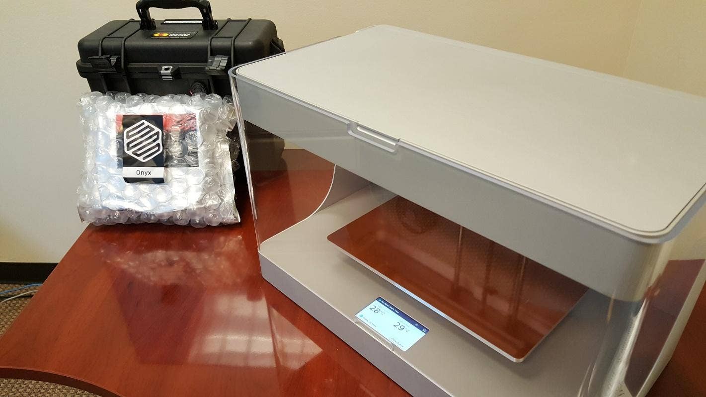
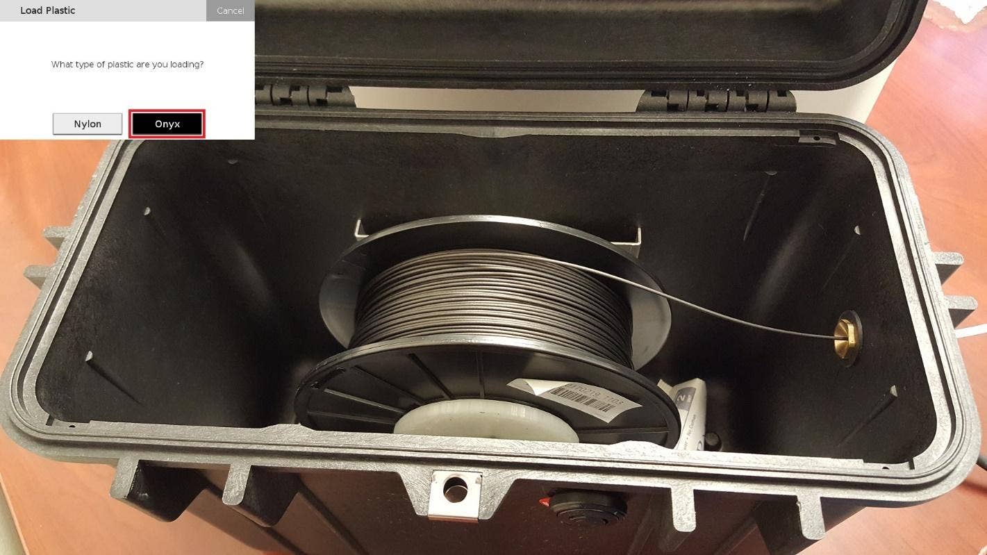
To get started with the Mark Two, we will first be un-packaging and loading our plastic. Although the Mark Two can print with nylon, we have chosen to print with Onyx, which is a nylon that contains chopped carbon fiber. If you would like to learn more about Onyx, feel free to navigate here: https://markforged.com/onyx/
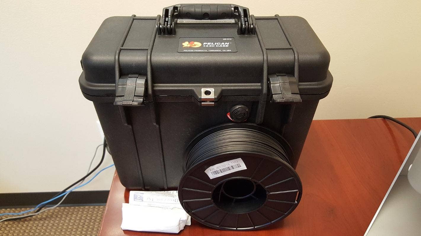
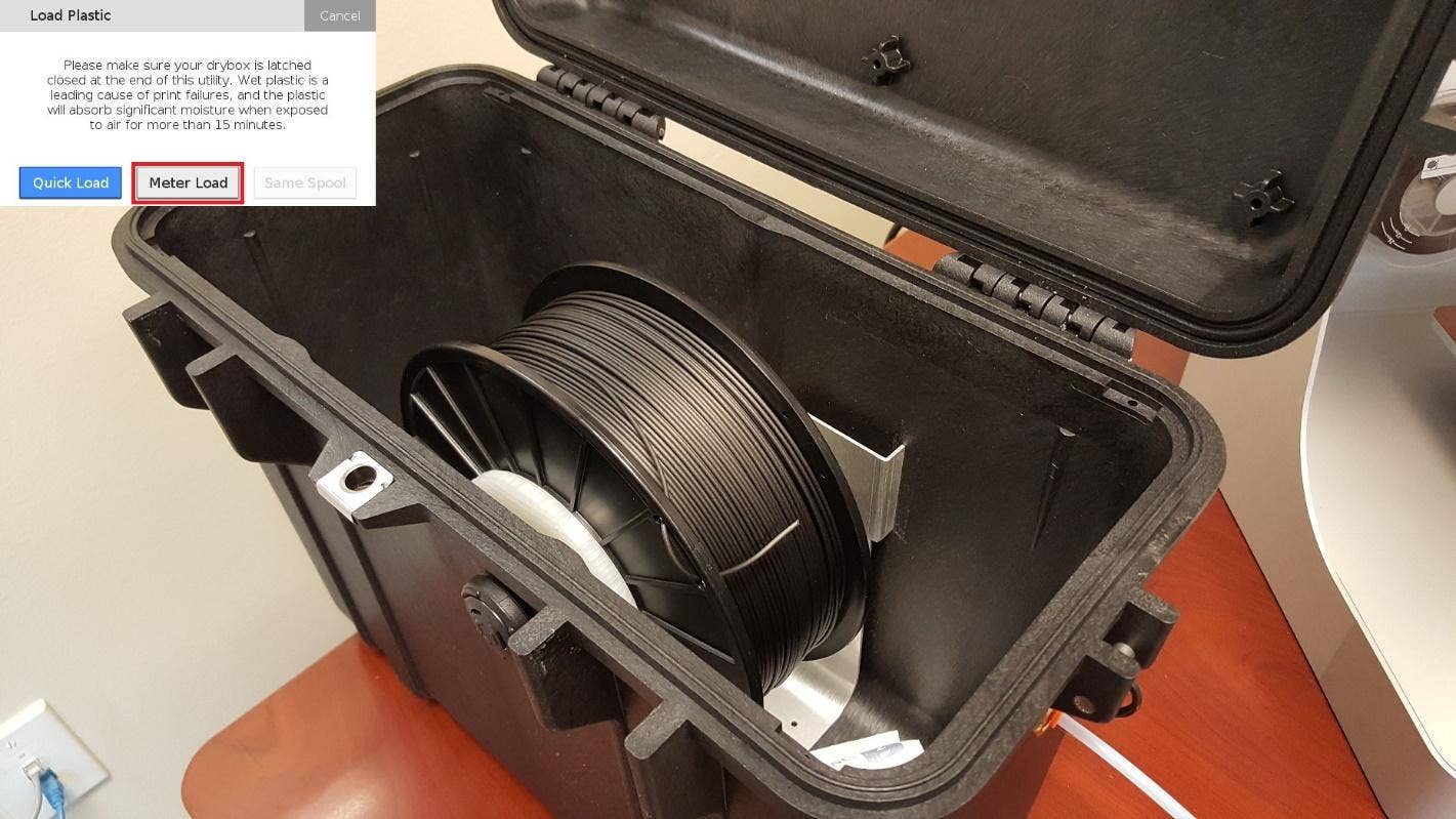
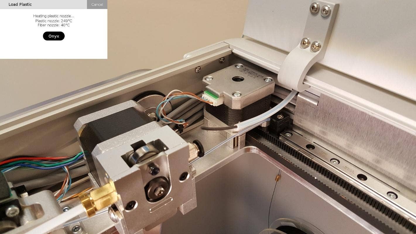
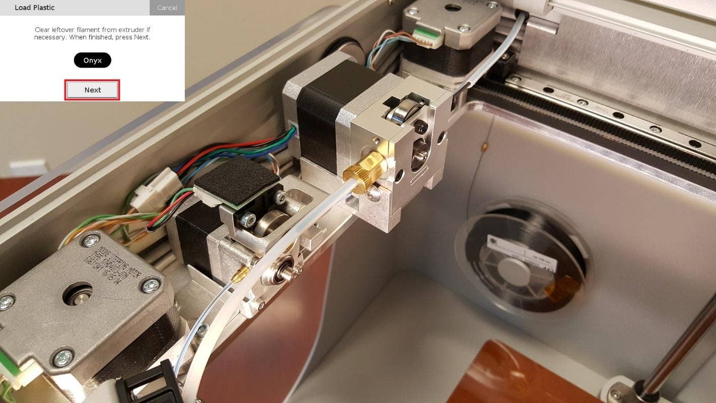
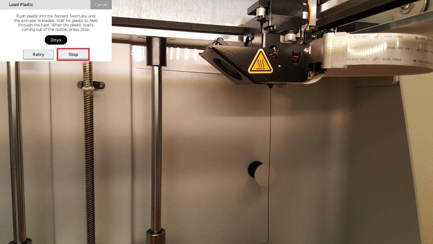
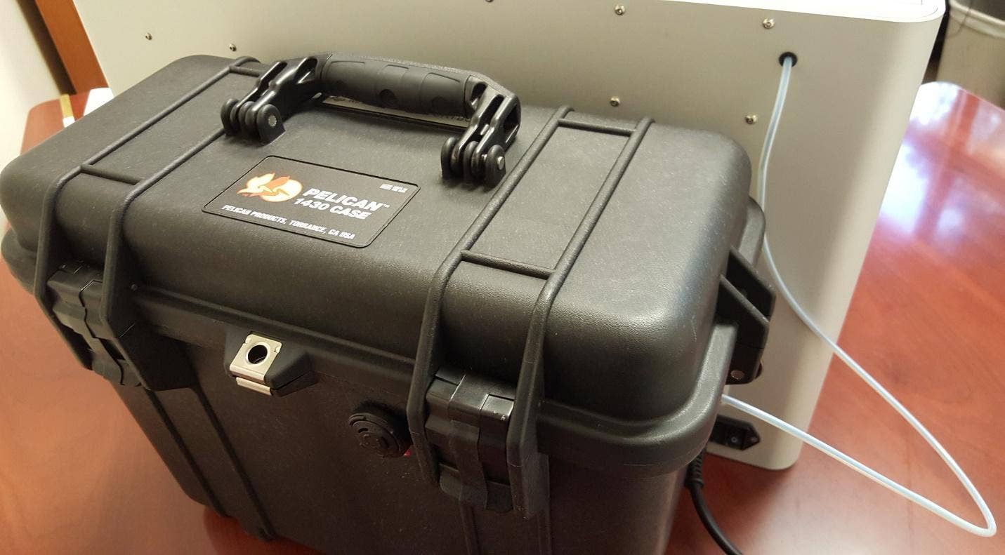
As is the case with nylon, Onyx is susceptible to moisture, so it will need to be loaded into the custom Pelican dry-box that Markforged provides. Once the material is loaded into our printer, we can utilize an on screen utility to walk through the process of loading the fiber. The following series of pictures will walk through the steps that were taken.
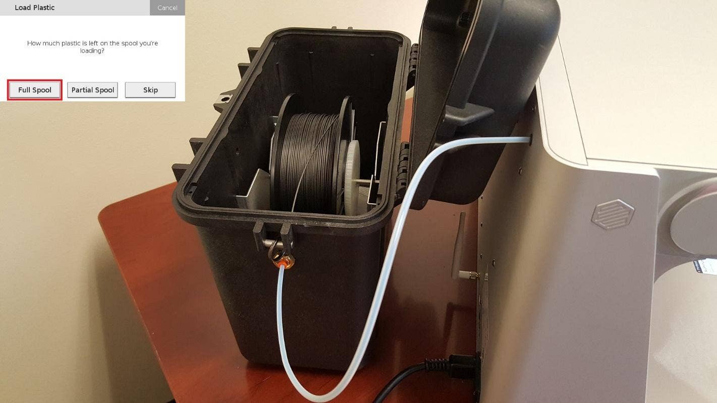
With the Onyx loaded, we now have the ability to print using only this material. Many Markforged printers also have the ability continuous fiber filament, and our Mark Two can inlay all of the fiber types available through Markforged. If you’d like to review the types of fiber that are available, including some of their advantages, you can do so here: https://markforged.com/materials/
As shown in some of the above pictures, we have already loaded a spool of Carbon Fiber. Since this material is not as susceptible to moisture, the spool is housed inside the printer.
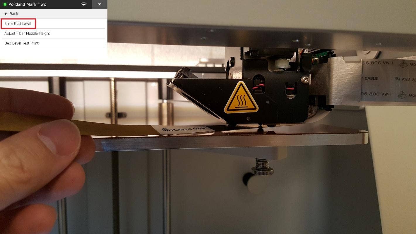
With both materials loaded, we can move towards printing a part. In order to ensure that our print comes out correctly, we will now level the print bed using the included leveling shims. As was the case with loading material, an on-screen utility walks through how to level your print bed.
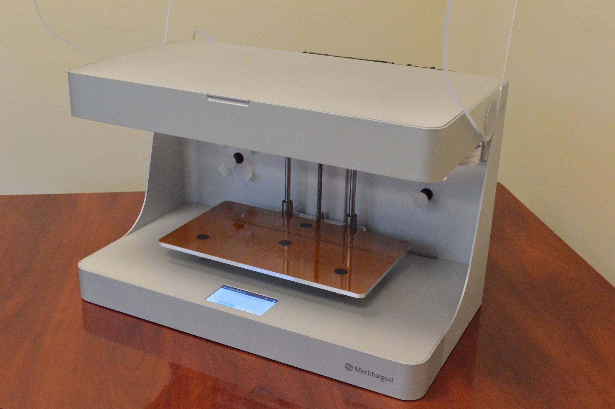
Markforged also includes a utility that helps to confirm a level print bed. This utility prints several small circles in different areas of the print bed. When the test print is finished, we verify consistency and smoothness across all the circles.
With our material loaded and the print bed leveled, we are now ready to set up our print with Eiger.
Printing with Eiger
As mentioned near the beginning of this content, Eiger is a cloud based slicing software that was developed by Markforged. It is used to customize and set up your prints, and can be accessed via the Google Chrome internet browser. The utilization of the Chrome browser allows Eiger to be accessed from a wide range of devices and operating systems. You can learn more about Eiger by navigating here: https://markforged.com/eiger/
In order to customize our print, we will first want to import the STL of our part. One of the ways to accomplish this is to simply drag and drop our file into the Eiger window, although Eiger does also allow you to browse for local STL files.
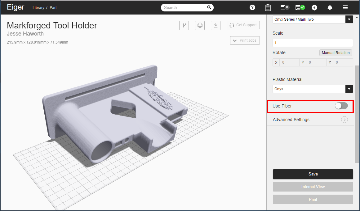
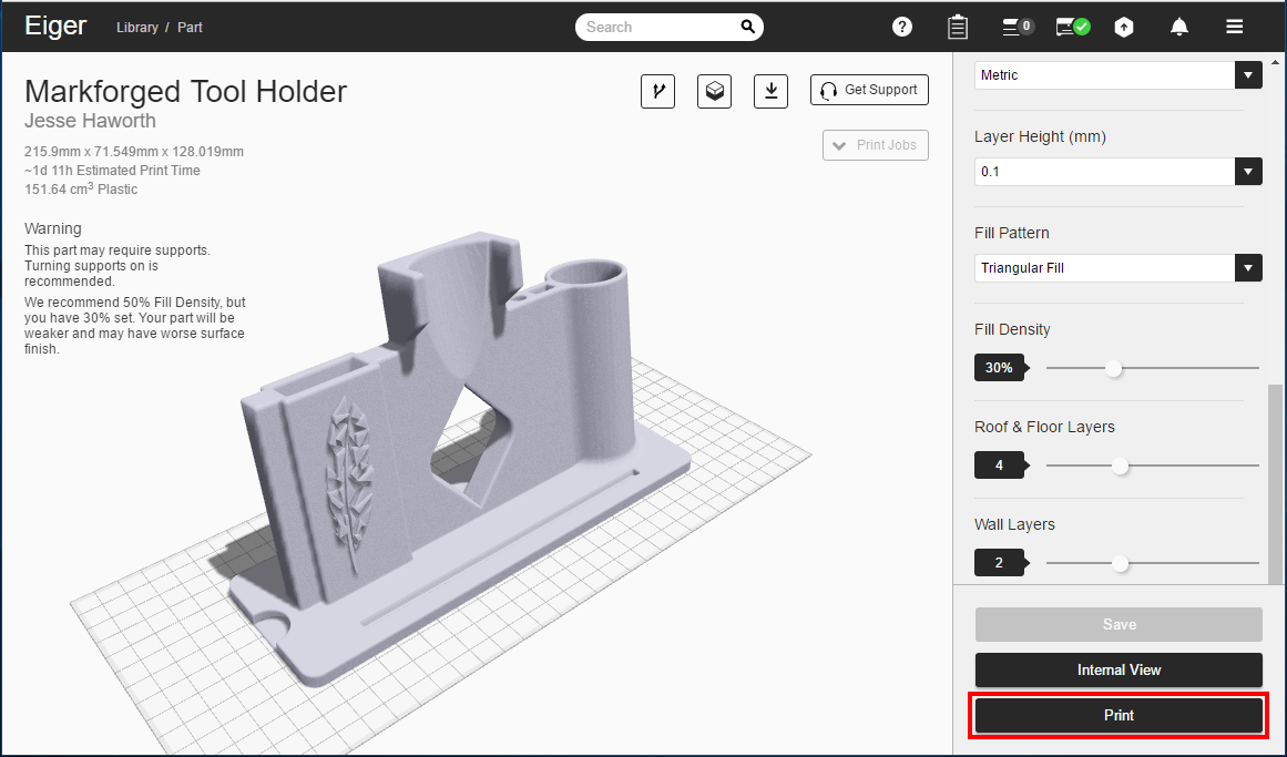
To demonstrate some of the options available in Eiger, we will be using a version of our tool caddy that is covered in Part 2 of this series. In general, the tool caddy will not be subject to any abnormal stressors, so we will not be inlaying any fiber for this particular part.
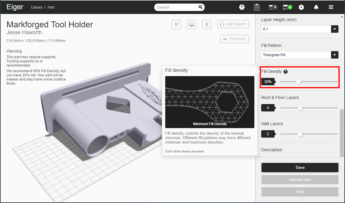
An additional item that can be customized is the infill percentage, which is the amount of internal part space that will be occupied by plastic. The default value for this percentage is 50%, meaning that half of a part will be filled by plastic infill. In almost all cases, the default value of 50% is recommended, although for this part, we will reduce the percentage to 30% to save plastic on a stationary item.
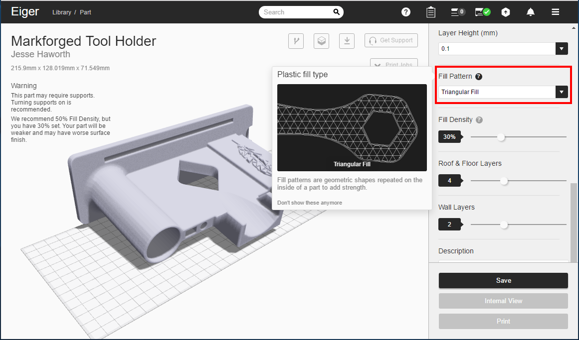
We can also change the infill pattern, although the default “triangle” pattern will work just fine for this case.
Lastly, we will change the orientation of the part by clicking on the bottom face, aligning it with the print bed. Printing in the correct orientation can help reduce print time and how much material is used.
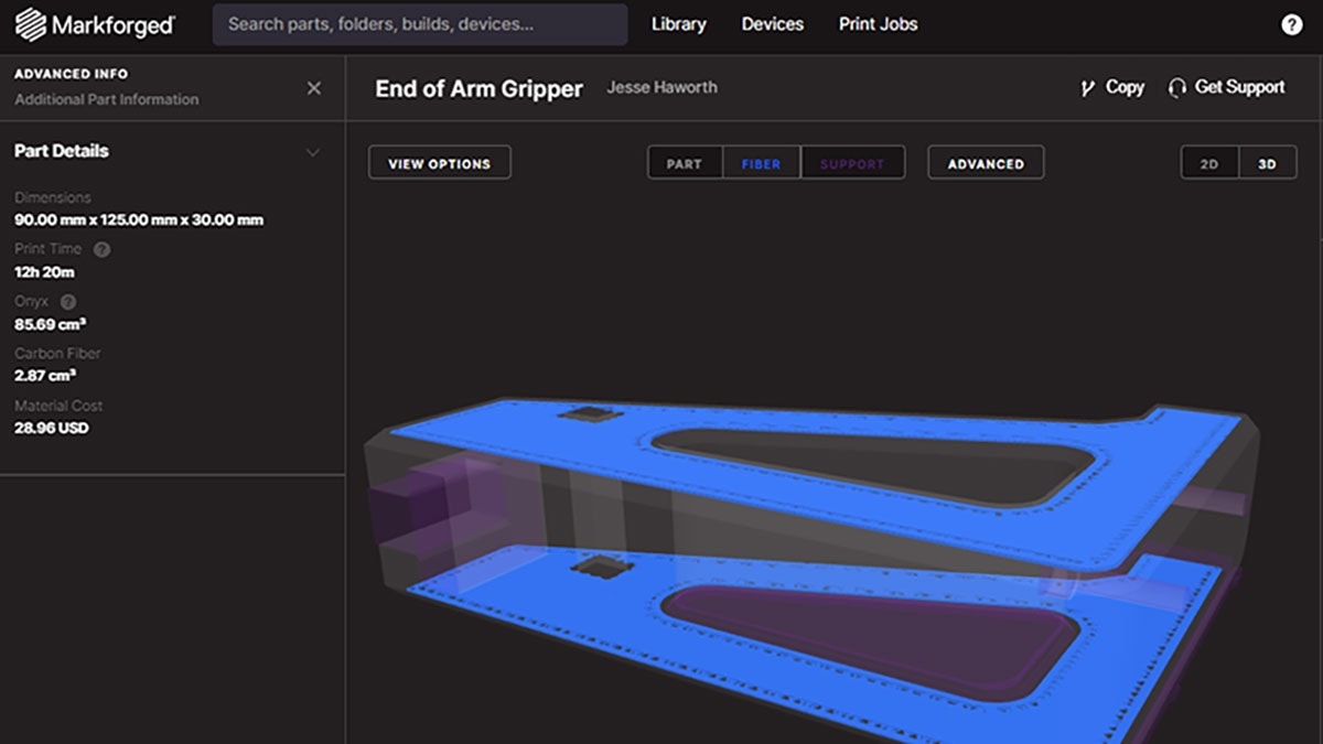
We can now begin the printing of our part. If we wanted to customize the fiber layout or check on how an individual layer will print, we could click on Internal View. To print the file, all we would need to do is click Print. Since Eiger has the ability to send us e-mail notifications when a print is finished, we were able to leave the printer knowing that we would be updated when our part is ready.
Once a print is finished, all we would need to do is remove it from the print bed using the included scraper. No post processing is required to use parts that are printed from Markforged printers, other than removing any support material that may have been included.
Check out Part 2 of this series, where we cover some of the design changes that were implemented while working on the tool caddy project. We will also take a look at the finished product in use!
For more information, check out our YouTube channel, get a 3D printer quote or contact us at Hawk Ridge Systems today. Thanks for reading!