I’m sure that those of you who are just getting started with CAMWorks
are making full use of the Automatic Feature Recognition (AFR) to define the
features to be machined and program your parts, right? If you aren’t, this is
just one of the many great features of CAMWorks that can save you time and
increase efficiency when you are programming your parts. There are instances,
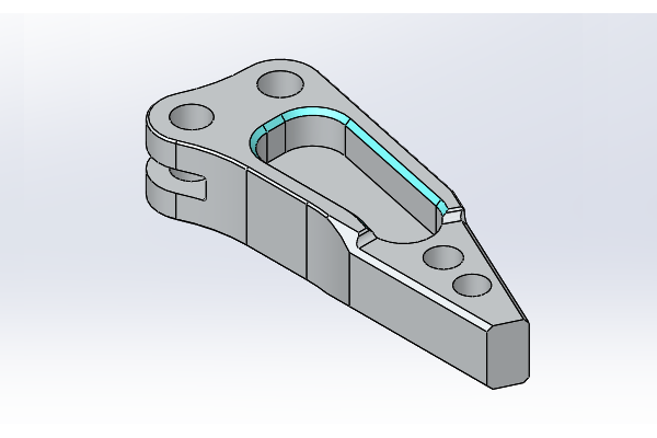
however, where it is required to define features manually. In this example we
will be taking a look at a part that has a pocket with a chamfer.
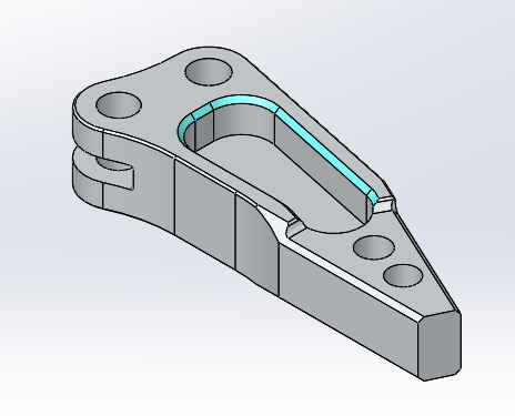
The stock and material are already defined using a sketch of the outline of
the part. When we run AFR on the part by clicking the
Extract Machinable Features button, CAMWorks will detect the
pockets, along with the other features, depending on your settings. If the
features with the chamfers are not recognized, this may be a result of the
“Tapered & Filleted” Feature Types being unchecked in the CAMWorks Options
under Mill Features. Having this option checked will allow CAMWorks to detect
the pocket and will use the default ‘Rough Finish’ strategy to machine it.
However, we still need to define the actual chamfer to be machined.
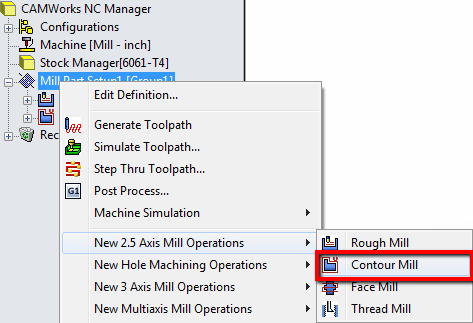
To do this, we will insert a second Contour operation. Under the CAMWorks
Operation Tree, Right-Click on the machine setup and choose
New 2.5 Axis Mill Operations > Contour Mill.
Select the pocket from the list of features to link the Contour operation to,
and click OK. Right-click the new Contour operation and select
Edit Parameters. First, select a tool to cut the chamfer. In
this example I chose a 3/8” 90Deg countersink. Next, switch over the Contour
tab and click the check-box to enable Chamfer Machining. This
is where you dial in the options to machine the chamfer.
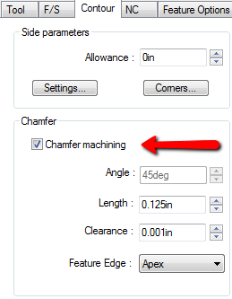
The angle parameter should automatically be set based on the tool that you
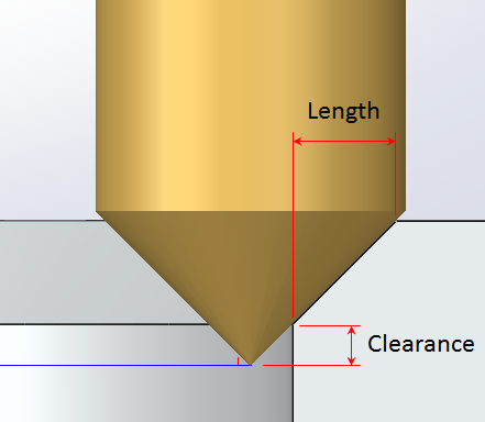
have selected, and in this case it’s 45 degrees. The length of the chamfer is
the horizontal distance from the vertical wall of the feature and where the
chamfer meets the top face. The chamfer we have here is 0.125”. It’s important
to pick a tool that’s large enough to cut the chamfer (radius of tool must be
larger than the length of the chamfer), otherwise you will get a warning and
no toolpath will be generated. The clearance parameter controls how far the
tip of the tool goes below the bottom edge of the chamfer (see illustration
below). If you want to offset the tool a little lower to prevent machining a
lip, add an offset such as 0.001”. You also have the option to drive the
toolpath based on the Apex or the Outer Edge of the chamfer.
Once all your settings are configured on how you want to machine that chamfer,
you can save out the operation plan for that specific feature. That way you
can re-use the exact same strategy to machine other features using the same
parameters and increase efficiency on the next feature/part we need to
program. Don’t forget to check out our
YouTube channel
for more useful tips!