Knurling is a type of surface finish commonly desired on precision tools and
other instances where additional hand grip is required on a machined part. In
practice, knurling is achieved by pressing a dedicated knurling tool into the
rotating workpiece. For this reason, it may not be necessary for manufacturing
purposes to model the knurling explicitly in CAD- many times a simple callout
on a drawing for a knurled surface may suffice.
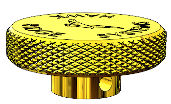
If it’s desired to have an accurate representation of the product in CAD for
purposes such as photorealistic rendering, however, then it may be necessary
to model the actual knurled geometry. This article and companion video will
focus on a technique to achieve this, and some performance considerations.
 |
The first step to creating the knurled surface finish is to create a sketch to
represent the knurl tool profile. In this example, I used a diamond shape
placed with its center coincident to the outer diameter of the cap, and the
width controlled by an angle dimension of 5 degrees. Compare against your
particular knurl tool for specifics.
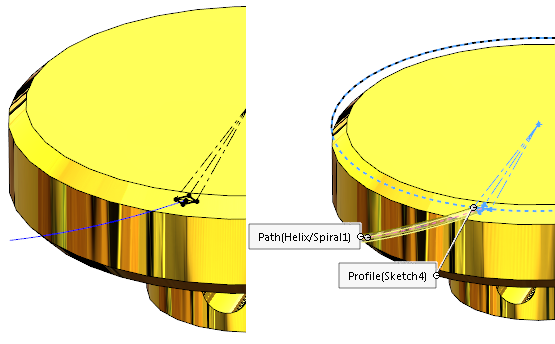
The second ingredient required is a helical path, which the profile will
eventually be swept along for a cut. To create the helical path, first create
a sketch on the same plane used to create the profile, and
Convert Entities of the outside edge of the cylinder. It is
important that this sketch only contains a single circle.
 |
Then, use the Helix/Spiral feature under
Features -> Curves -> Helix/Spiral and select the
sketch containing the circle. Use the Helix option and adjust the start angle
and pitch values to align the Helix with the profile. In this example, the
profile was aligned vertically with the origin, which aligned with a start
angle of 180 degrees. The profile could alternatively be sketched after
generating the Helix to ensure they line up.
Once the profile and path are created, create a
Swept Cut feature using these selections and the “Minimum
Twist” option.
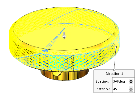
All that is left then is to Mirror and
Circular Pattern the resulting Swept Cut to produce a
representation of the desired surface finish.
 |
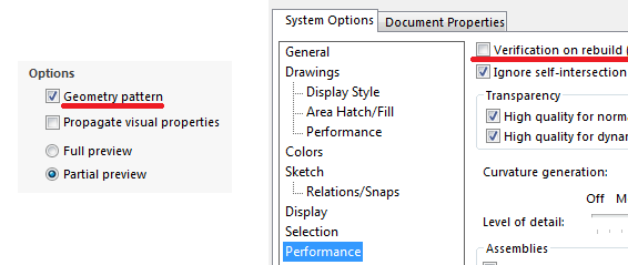
Generating textured surfaces by cutting away at the CAD geometry is a
computationally intensive process. To help minimize rebuild times there are
two key settings to pay attention to. The first is in the
Circular Pattern options. Use the option for
Geometry pattern which can reduce rebuild times significantly
for repetitive geometry.
The second option is a System Option accessible under the
Performance tab called
Verification on rebuild. Verification on rebuild can
drastically increase rebuild times on geometry such as this as it performs
more advanced geometry checks between each set of faces. It is recommended to
disable it on these types of parts or you may experience excessive rebuild
times.
 |
Also consider grouping these detail features together so they can easily be
suppressed. Whenever adding cosmetic detail like this, it is desirable to also
create a “simplified” configuration in case performance ever becomes an issue-
for instance, if dozens of these knurled pieces were necessary for a large
assembly.
There may also be alternative “lightweight” ways to represent the textured
surface, such as using a custom appearance with a Displacement Map. However,
this effect would only be visible in a photorealistic rendering – not within
SOLIDWORKS CAD.
For additional details on how this process can be performed, please check out
this YouTube video or see what else we have on our
channel, check out our
SOLIDWORKS page
or
Get a Quote
for SOLIDWORKS 3D CAD. Don’t hesitate to contact us at
Hawk Ridge Systems
today!


