If you ask a group of mechanical engineers what the important factors are in the products they design, you’re likely to find a majority that bring up the behavior of fluids. From the drag coefficient of a car to the pressure drop in a hydraulic manifold, designers in nearly every industry are looking for the next breakthrough in performance. So, it’s no surprise that CFD (computational fluid dynamics) software has become an important tool to aid in the design process ever since the first code was developed at Los Alamos National lab in 1957.
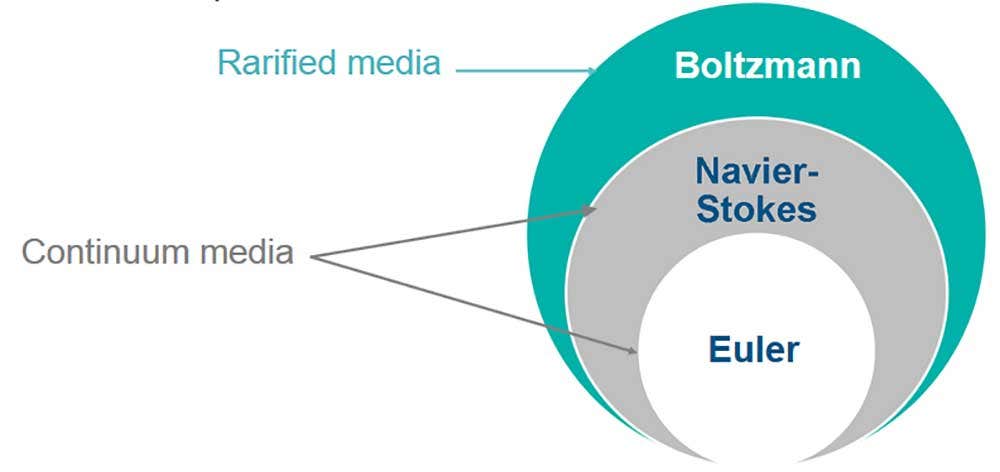
Users of SOLIDWORKS are likely familiar with the CFD capabilities that can be activated right from their design environment via SOLIDWORKS Flow Simulation, which has long been the most efficient way for these users to check such concerns. For many design projects, especially those involving heat transfer (such as electronic devices or heat exchangers), this process will continue to be the best for years to come. But, like all CFD programs based on the Navier-Stokes equations, there are some inherent limits to SOLIDWORKS Flow Simulation that prevent it from analyzing certain situations.
These limits are the barrier that a new CFD approach, called the Lattice-Boltzmann method, is meant to break through. This technique uses a particle-based approach that can calculate highly dynamic flows with detailed visualization of turbulence, even in non-continuous fluids such as near-vacuum environments or hypersonic airflow.
SIMULIA XFlow Overview
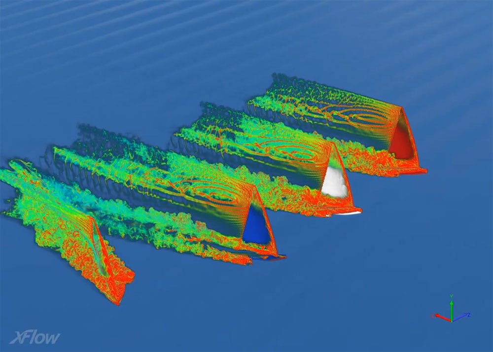
This technology is the foundation for a new CFD product called SIMULIA XFlow. Running on the Windows (or Linux) desktop environment, with optional connections to Dassault Systemes’ 3DEXPERIENCE Platform, XFlow can import a variety of solid CAD files and start calculating advanced fluid effects without traditional meshing. The Lattice-Boltzmann method combined with other advanced technologies such as liquid surface tension and free body motion allow XFlow to simulate everything from a boat riding the waves, to oil sloshing in a gearbox, to an aircraft executing flight maneuvers, and much more.
Even common design challenges can benefit from this technology. Veteran SOLIDWORKS users may recognize this classic ball valve example, showing how SOLIDWORKS Flow Simulation can predict internal pressure drop and flow rates. For assemblies that move, like this valve, the traditional approach is to batch run the simulation in multiple positions with the Parametric Study capability. SIMULIA XFlow, however, can take this example to the next level by dynamically simulating the valve opening or closing, and directly visualizing the turbulent eddies in the water as this happens:
While it’s not integrated inside SOLIDWORKS 3D CAD, XFlow does sport some of the same user-friendly benefits such as a modern GUI with both setup and results viewing, and automatic recognition of the fluid space and boundary layer. Performing an analysis can be as easy as importing a .STEP file, applying some boundary conditions, and hitting Run.
For more examples of how 3D design and validation tools can help your engineering processes, contact us at Hawk Ridge Systems and be sure to get SIMULIA pricing today!