
SOLIDWORKS Flow Simulation is a powerful, general-purpose Computational Fluid Dynamics (CFD) package integrated directly into the SOLIDWORKS CAD environment.
The base package of Flow Simulation includes the ability to simulate fluid flow, heat transfer, mixing of multiple fluids, and rotation. This combination of features makes it well suited for analyzing a variety of industrial equipment. We’ll look at a number of cases in this blog article and associated webinar.
Mixing Problems
Mixing of fluids can be handled for a static mixer by definition of multiple different inlet flow conditions, or with a rotating agitator by definition of a “rotating region”.
In the mixing tank example below, two fluids are included in the analysis and are initially separated in the tank
The analysis is run as “time-dependent” so that the concentration of the fluids can be monitored over time, and the torque and power of the agitator can be measured to compare motor requirements under various designs.
For more complex problems that involve free surface, multiple agitators, or reciprocating motion, SIMULIA XFlow is a standalone tool that should be considered.
Heat Exchangers
Enabling the “Conduction” option when creating a SOLIDWORKS Flow Simulation project allows definition of heat sources and simulating the effects of conjugate heat transfer. A common example is the shell and tube heat exchanger. A simple water to air heat exchanger is pictured below, though complex models with hundreds of tubes may also be analyzed.
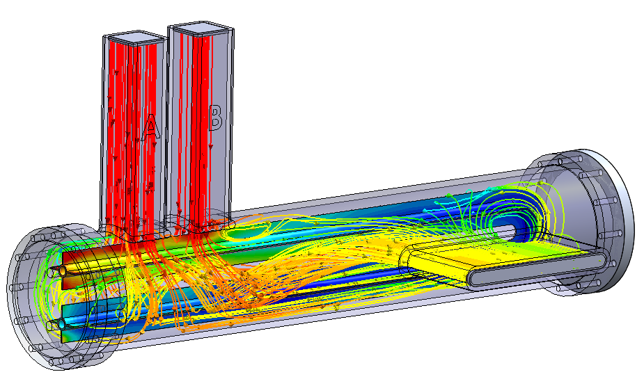
The definition of a “Fluid Subdomain” allows representing distinct regions of fluids. In this case the default fluid is air, and a Fluid Subdomain of water is applied within the copper tube.
The heat transfer rates can be quickly extracted, along with pressure drops across the exchanger.
Air Handling
Air handling devices and extraction hoods such as those pictured below can be analyzed using the core features of SOLIDWORKS Flow Simulation. “Porous Media” definitions allow simplfiied representations of filters, grates, and other complex media.
The optional HVAC add-on module for Flow Simulation allows tracking of human comfort parameters, and the provision for “tracer studies” which allow injection of contaminants into an existing Flow study.
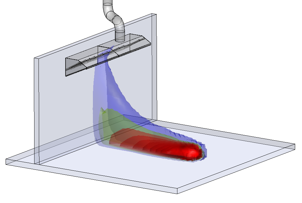
In the figure above, tracers of carbon monoxide are injected from a source near the extraction hood. Isosurfaces of carbon monoxide are plotted to visualize regions of high concentration.
On-Demand Webinar: Streamlining the Analysis Process
As Industrial Equipment is commonly built-to-order, streamlining the analysis procedure to be able to get results quickly is crucial. There are multiple tools for this in the software: “cloning” analyses between multiple configurations, using “parameteric studies” to quickly evaluate design variations, or creating custom “project templates” to apply standardized setup on new models.
These techniques, along with the use cases above are explored in more detail in our on-demand webinar.
Contact us if you’d like to learn more about validating your Industrial Eqiupment. Beyond SOLIDWORKS Flow Simulation, we also SIMULIA XFlow for problems with complex body motion and free surface interactions, and SIMULIA Fluid Dynamics Engineer for cloud-connected, cloud-solving CFD.