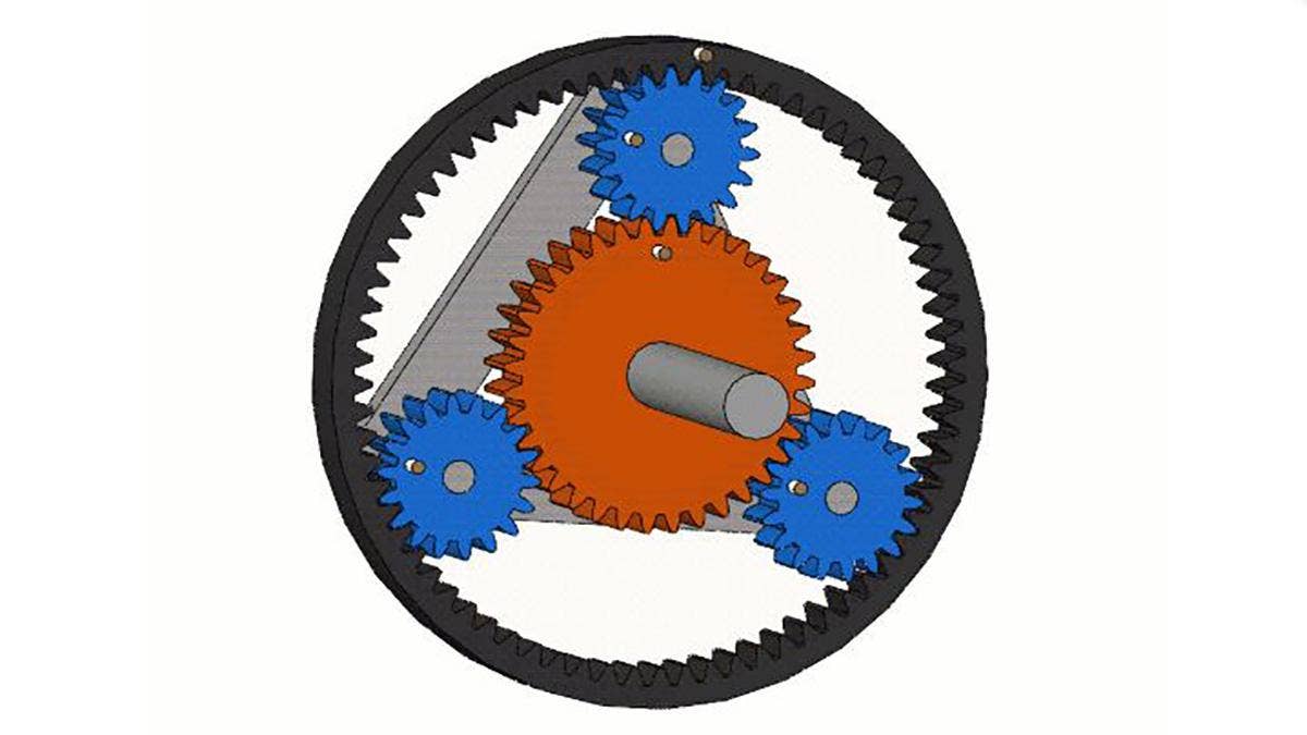
Planetary gearing is a compact alternative to standard pinion-and-gear reducers and is used in a wide variety of applications to provide high torque. We are going to go over the setup of a planetary gear assembly in SOLIDWORKS that will allow us to demonstrate the motion of the three drive types of this system.
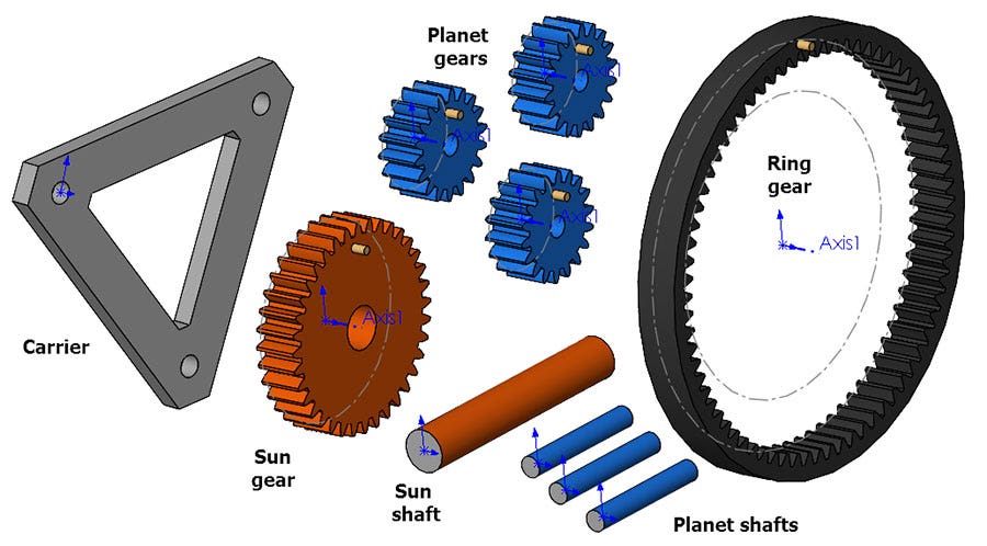
To set up our planetary gear system,first we will insert all of the necessary components into a new assembly document:
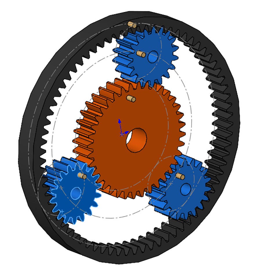
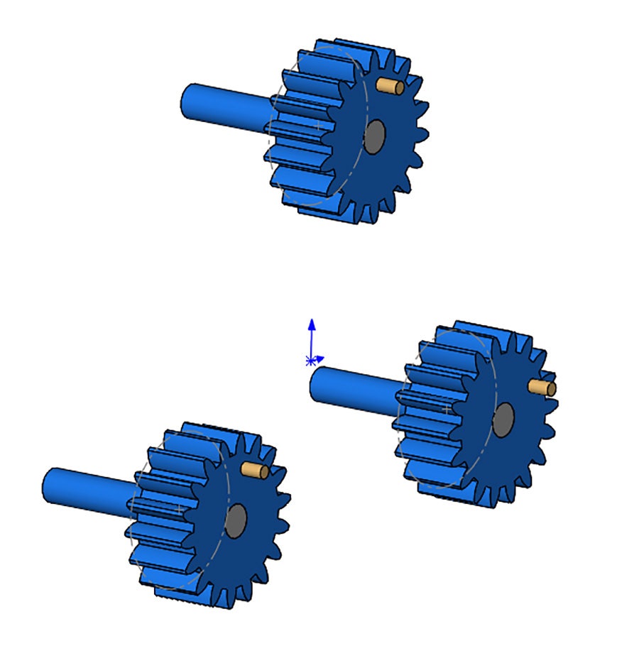
- 3 x planet gears (blue)
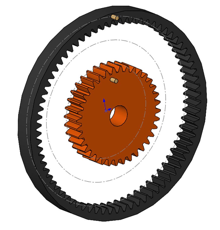
- 1 x sun gear (orange)
- 1 x ring gear (black)
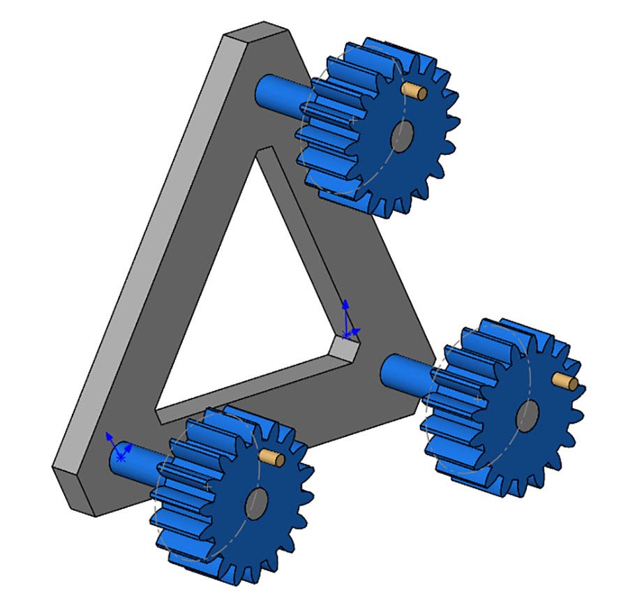
- 1 x carrier
- 3 x carrier shafts
- 1 x sun shaft
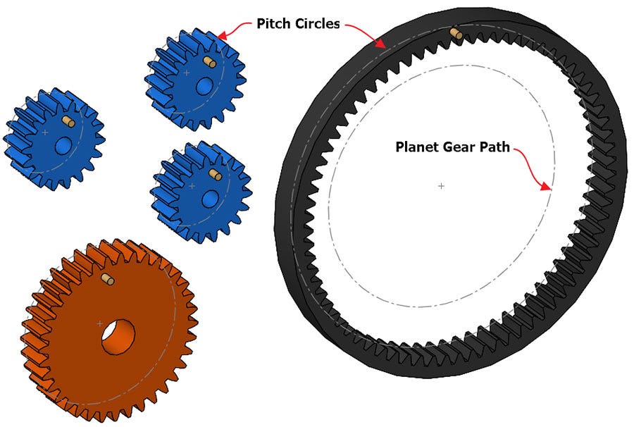
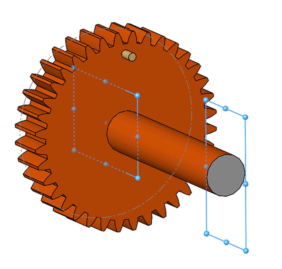
In each of the gear part files, pitch circles have been created as construction circle sketches. The Ring gear has an additional construction circle drawn to guide the path of the Planet gears, this will be key to correct motion and will be called the Planet Gear Path.
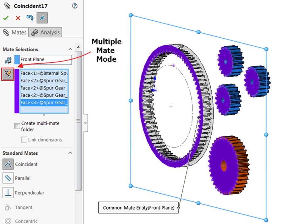
To start assembling the gear system, we will mate the back face of each gear Coincident to the Front Plane of the assembly (make sure that none of the parts are fixed in-place, if so right-click the part and select Float). To speed up this process, use the Multiple Mate Mode button, and select the Front plane as the common reference.
Next, mate the center of the pitch circles on the Ring Gear and Sun Gear to the Assembly origin, they should both be able to spin.
Next, mate the center of the pitch circles of the Planet Gears coincident to the Planet Gear Path sketch.
Now, mate the Carrier shafts to the centers of each Planet Gear (Concentric) and flush with their front faces (Coincident).
Get the Carrier in place by adding Concentric mates to each Carrier Shaft, and one Coincident mate to bring it flush with the back of one of the shafts.
Lastly, mate the Sun Shaft into place with another set of concentric and coincident mates (this part is not actually necessary to show the motion we are after). We want the Sun shaft to rotate with the Sun gear, so we will also mate Reference Planes together with the Coincident mate to link the rotation of the two parts.
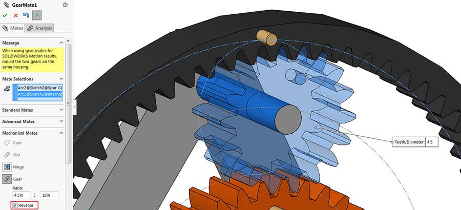
Now we are ready for the Gear mates. Select the Pitch circles drawn on each gear to define the Gear mates, this will define the gear ratios, though cylindrical faces on the gears could also be used and ratios can be manually overwritten. Add Gear mates between the three Planet gears and the Ring gear and one gear mate between a single Planet gear and the Sun gear (this is all that is needed for the complete gear motion). While making the Gear mates, be sure to test each and ensure that the spin directions are correct, use the Reverse checkbox in the Mates Property Manager to fix if necessary. Also, do not worry about making the gear teeth mesh correctly, we will fix this next.
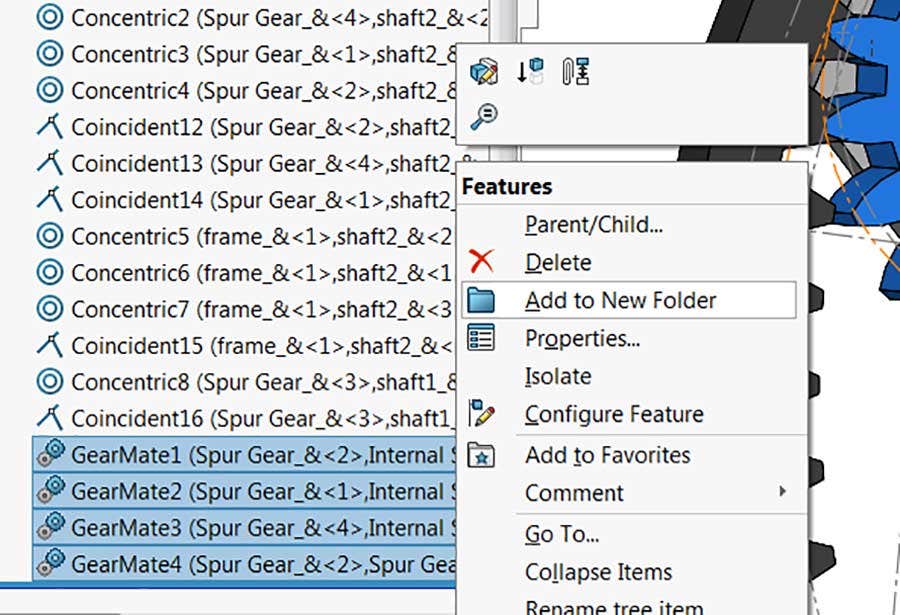
To group the gear mates into a folder: shift-select the Gear mates, right-click, and select Add to New Folder. Drag it to the top of the Mates folder for ease of access.
Next, we will make another group of mates to help position the gear teeth correctly, this can be done by creating Parallel (or Angle) mates between reference planes on the gears and reference planes on the assembly. Depending on how the gears were created, this should get the teeth to mesh correctly, in this assembly the Top planes are aligned with teeth and the Front planes aligned with gaps, so getting precise alignment is easily attained with parallel mates. Using mates for the alignment is preferable to dragging them into place because they can be used in the future if realignment is necessary. Don’t forget to add an additional mate to align the Carrier. Group these mates into a folder as well. Once aligned, suppress the entire folder.
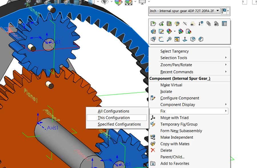
Now it’s time to create configurations for the three modes of movement. For each configuration a component will be fixed in place, before fixing any component be sure to unsuppress the alignment mates to ensure these components are in the correct position and then suppress the alignment mates once again. Add a configuration called “Ring Gear Fixed.” Right-click the Ring Gear and select Fixed, This Configuration only.
To test motion, rotate the planetary gears by the Carrier for best results.
For the second configuration, copy and paste the Default Configuration and rename it “Sun Gear Fixed.” Align the gears and fix the Sun Gear in this configuration only.
Repeat the process, naming the third configuration “Carrier Fixed” and fix the carrier only in that configuration.
If at any point after switching configurations the gear teeth do not mesh correctly, first suppress the gear mates and then unsuppress the alignment mates. After the gears are realigned, you can once again suppress the alignment mates and unsuppress the gear mates. Remember that the gear teeth do not have to mesh correctly for the motion of the planetary gear system to be observed, though it will affect evaluation tools such as interference detection.
In this blog we looked at how to set up a planetary gear system with realistic motion using gear mates, as well as mates between reference geometry and sketches. Check out our website to learn more and discover other SOLIDWORKS features or contact us at Hawk Ridge Systems today. Thanks for reading!