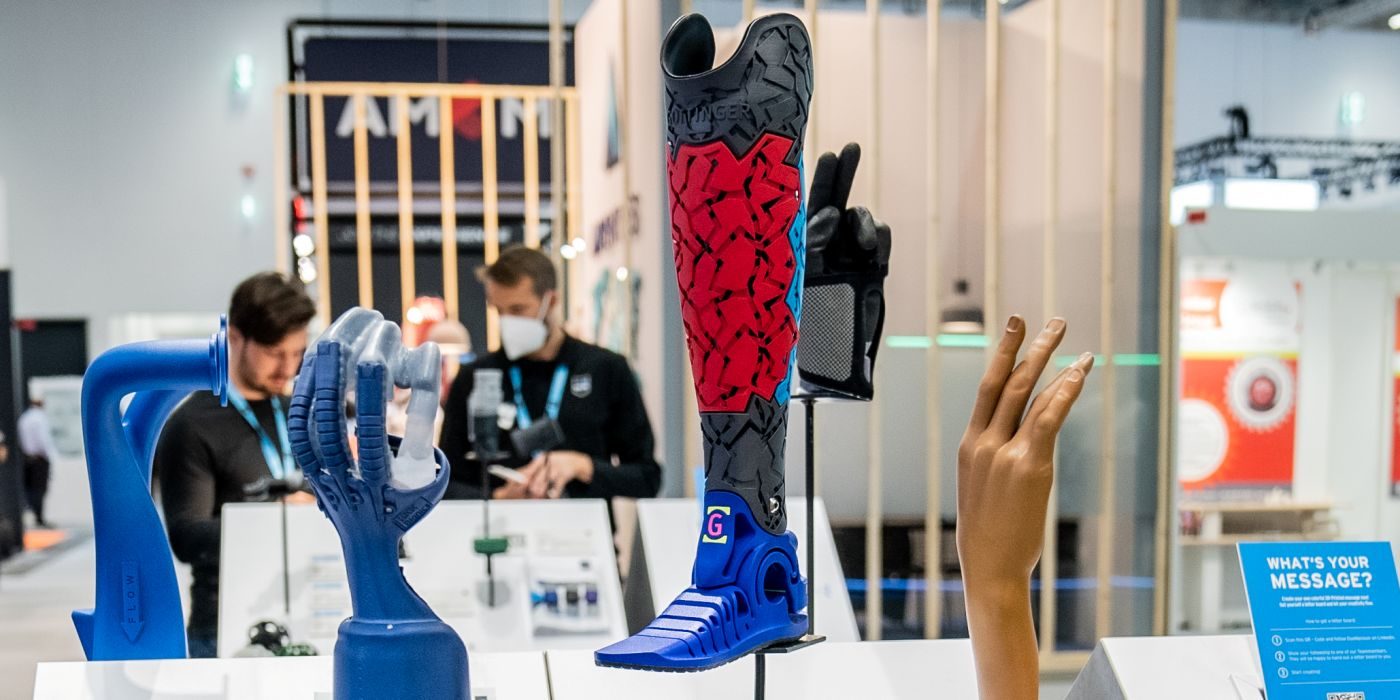
At Hawk Ridge Systems, we are always working on applications and sample parts to showcase how powerful additive manufacturing can be. One of our latest is projects has been testing the best methods to make pure copper bus bars.
It has been clear that the transportation industry is moving toward electrification at a pace that rivals the automotive boom of the early 1900s. As a result, custom parts like bus bars for testing in pre-production (as well as end use for aftermarket) will be required. This project will compare 3D printing a final ready-to-use bent bar printed on the Markforged Metal X, forming from a flat pattern that is 3D printed, and traditionally cut copper.
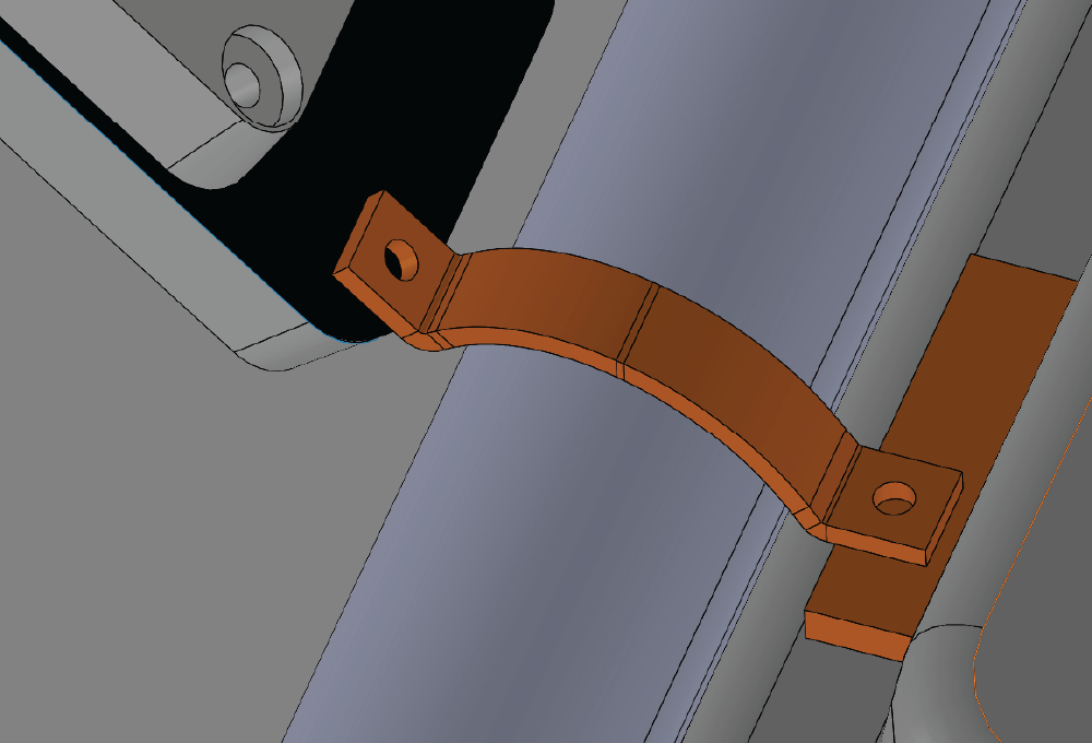
In our example model, we are wanting to show how space constraints create a challenge for bus bars. The bus bar has a 45 degree bend, large central arch to avoid a fluid line, a 90 degree bend to connect our smaller module which sits at a 45 degree angle and is offset from each bolt. This compounded situation makes prototyping in traditional methods challenging for those engineers who don’t have hands on experience with bending metals.
With the Markforged Metal X we are able to 3D print in pure copper filament, which goes through a sintering cycle to create a true metal part. Post sintering the part has a density greater then 95 percent with only a slight reduction in electrical and thermal conductivity, compared to a traditionally bent copper sheet metal part. From our customers feedback, a 3D printed bus bar has performed as well as a traditionally manufactured bus bar in their test enviroments and meet the design requirements.
Bending Dies Perfected with Markforged Simulation in Eiger
With the launch of the new Markforged Simulation software, we wanted to prove how useful this product is for a real use case. Additive manufacturing still proves to be a challenging prospect for all calibers of simulation software – this in turn can slow down the adoption of 3D printed products for end use. As engineers, you simply didn’t have the tools to show if a 3D printed product could stand up to your final goals until now.
With all designs, we must set requirements for what our goal is for the project. For this we wanted to set a goal for single operation forming and we are less concerned about the sharp corners and what would be acceptable for a final part. This is a tool for prototyping for our situation, but lets dive in and see how good it might actually be.
Forming copper – though not the stiffest material – does have an astounding 1.5kN (approx 225 lbs) of bending force required to make the tight radius bend at 3mm thick. We wanted to find out what the minimum design requirements would be and to do that we needed the new simulation function build into Eiger.
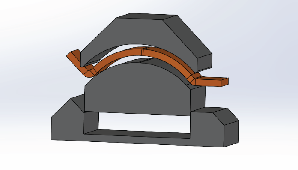
We focused on the upper forming die with this shape naturally taking the stress at two very small points at each end of the die. We need to find out if our slim design will be strong enough, or if we need to strengthen up the design before we start making the final fit and functional design.
Using Markforged Simulation
Within Eiger you find a new simulation button has appeared, which will use “as 3D printed” geometry to simulate basic loads. Infill pattern and density changes are part of the simulation, giving greater accuracy and better predictions than CAD simulation software can provide for 3D printed parts.
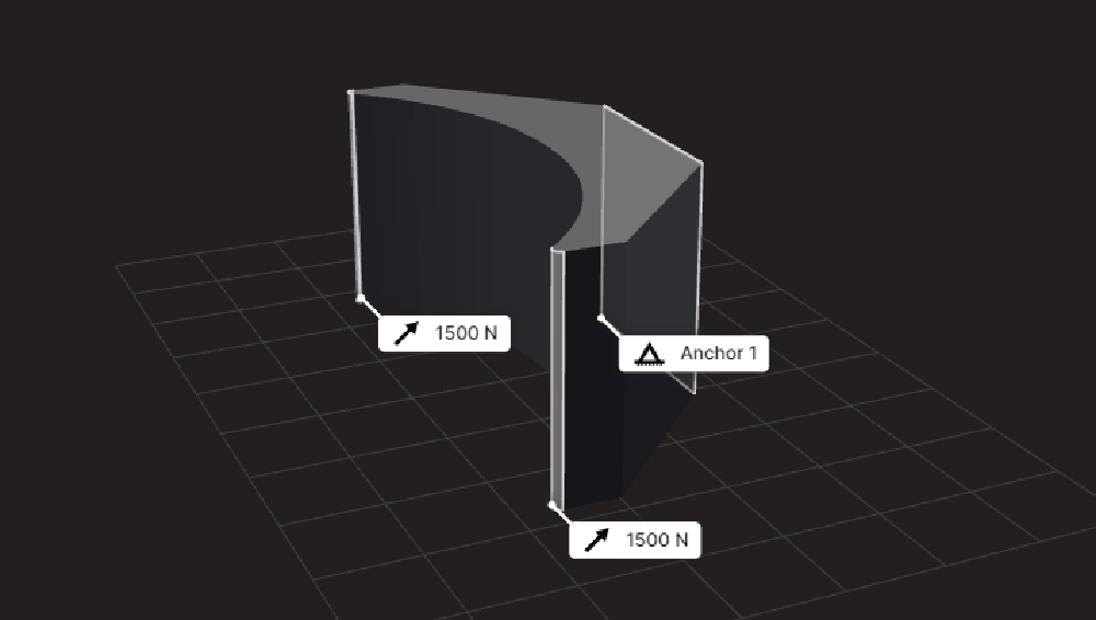
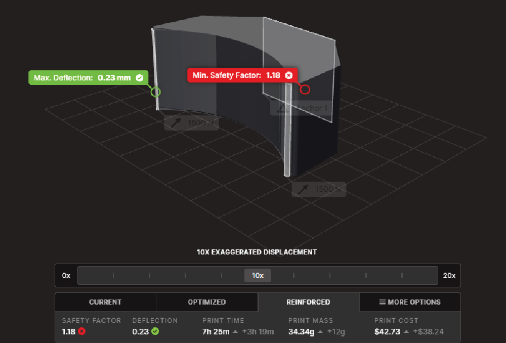
We selected our primary surfaces that will have the greatest load points and an anchor surface to reference. 1500N was calculated from an online source for bending load calculations.
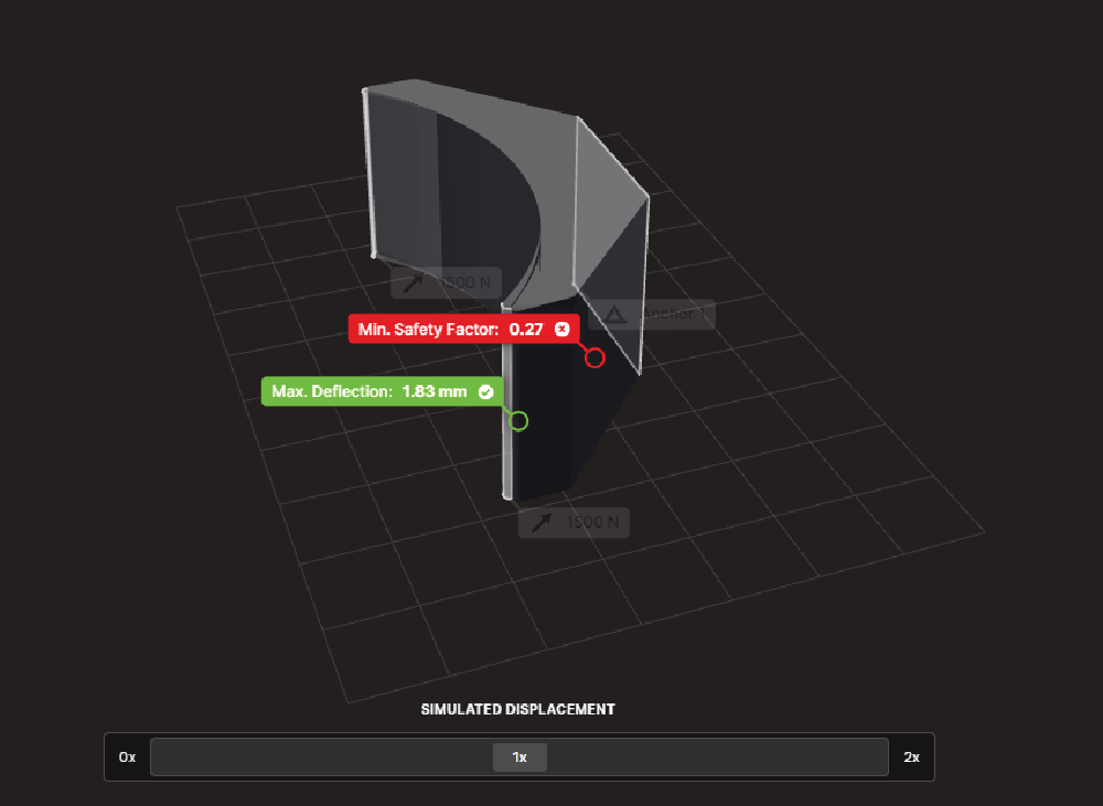
Our results from the initial simulation. Low safety factor and far too much deflection to accurately bend our bus bar.
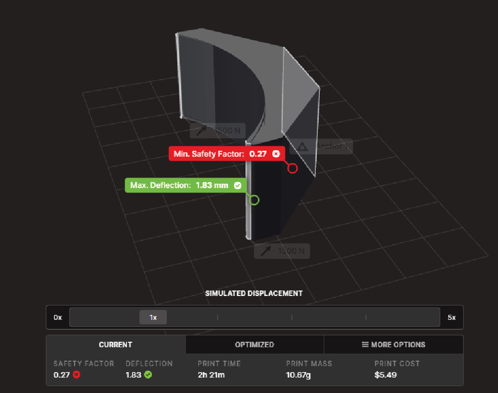
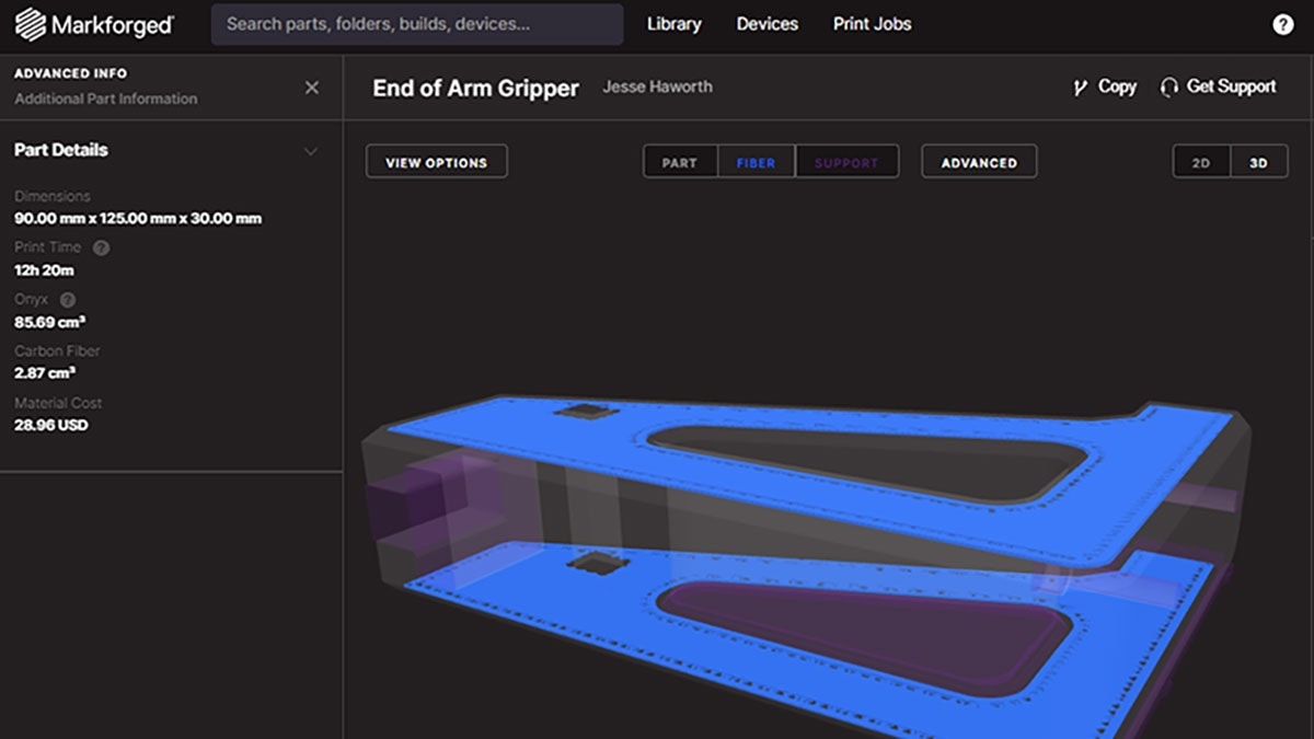
Within minutes, we had our new optimized results. Our “CURRENT” settings include an Onyx base with Carbon Fiber on the top and bottom surfaces in addition to a 37 percent triangular infill. This resulted in too much deflection for our requirements.
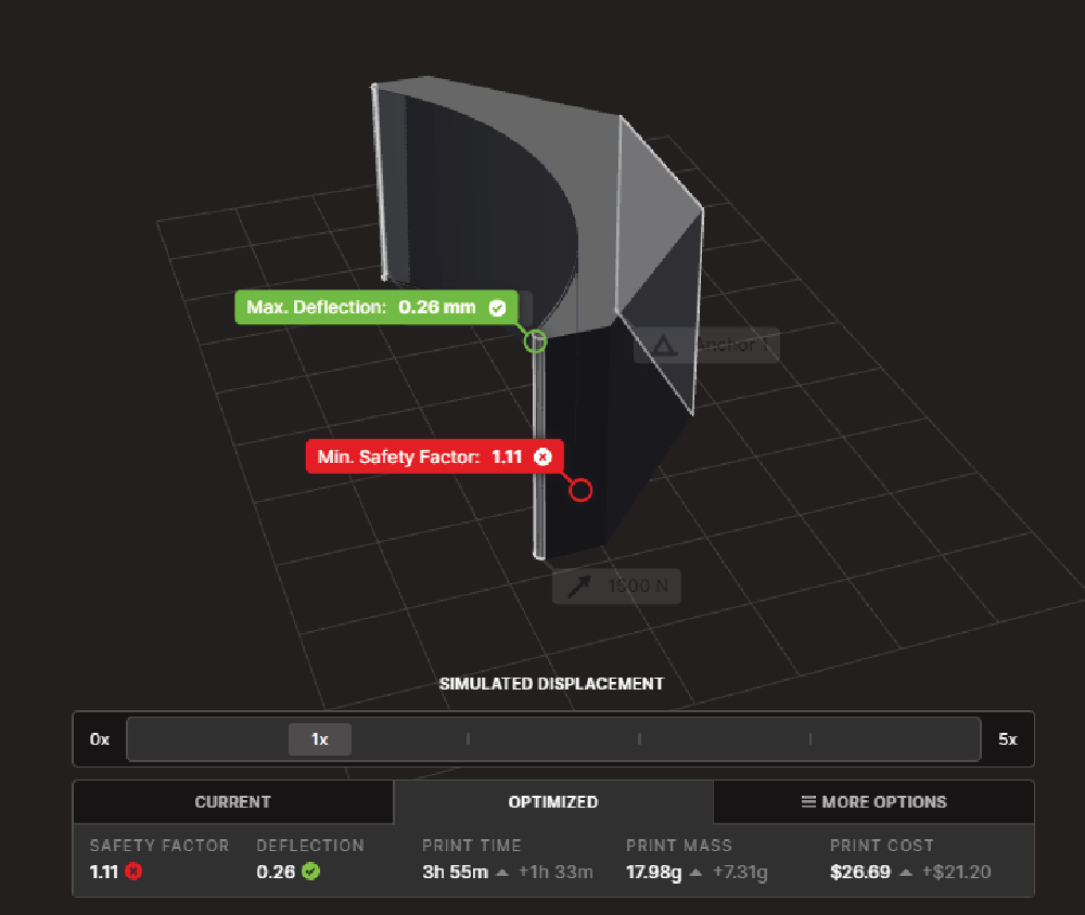
By selecting the “OPTIMIZED” tab, we get instant print-ready optimization. This is remarkably close to acceptable for our use situation. Our only potential concern is the safety factor being lower than two.
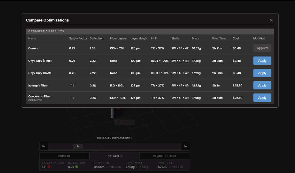
Under the “MORE OTIONS” tab, we get a list of suggestions based on multiple factors. From the list, we can see the Fiber options are the closest options to meeting our goals.
From the list shown above, we selected the Concentric Fiber optimized for print speed and lowest mass.
Though this design is extremely close to working, we think by changing the geometry we will help bring stiffer results and be able to lower our Carbon Fiber requirement – thanks to this helpful insight provided by Markforged Simulation.
Simulation Optimized
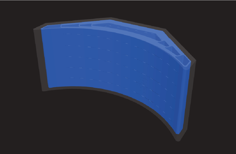
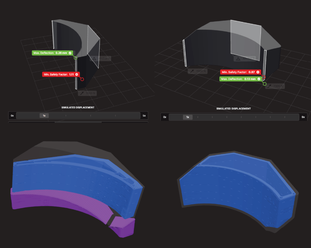
After reviewing the results from the first simulation we concluded, adjustments to make the forming die function within the set specifications were required still. In SOLIDWORKS, the thickness of the part was modified with an additional 5mm and exported to Eiger for simulation. In Eiger, two additional wall layers were added to increase the shell thickness.
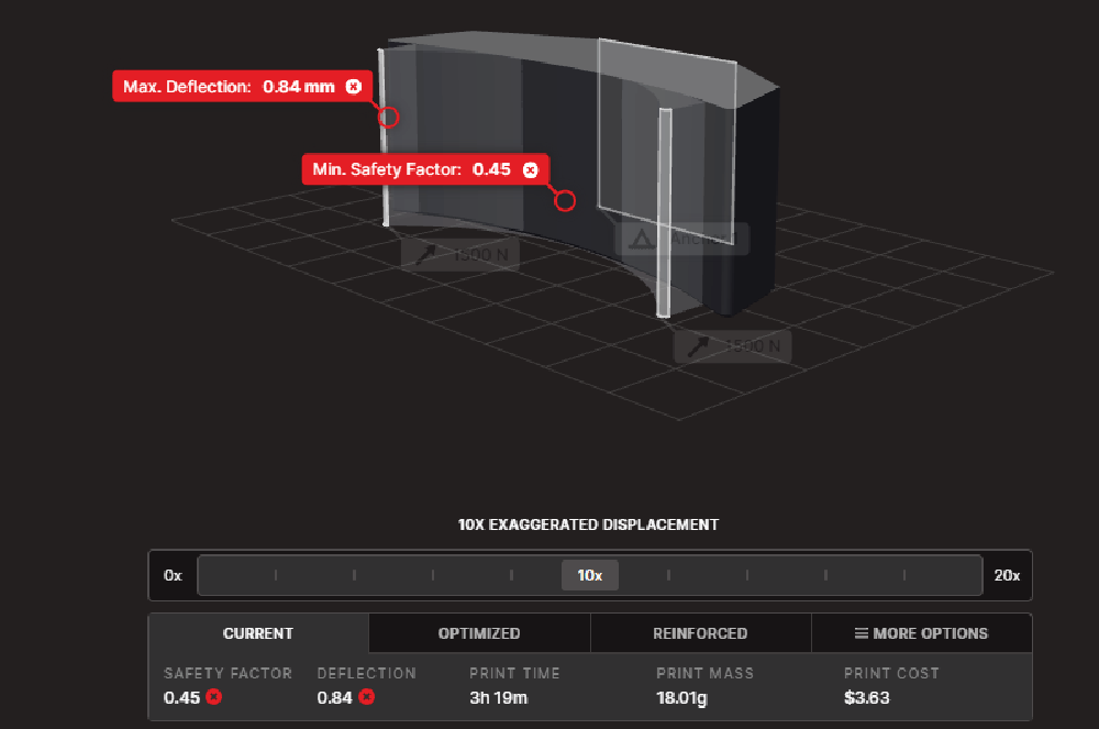
Using the same 1500N setup, this thickened eight wall layer Onyx only part is already far better with 3X less deflection than the original thin V1 design. The result is still unacceptable, however, with the target set to be 0.25mm deflection with a safety factor of two.
With similar results to the thin model, we applied the optimization to the part to review what could be the cause of the similar results.
After gaining insight and finishing the CAD model in SOLIDWORKS, we are going to test the original non fiber model and these final versions. From the data we collected, both should work with differing levels of rigidity and safety factor we want to see the real-world testing.
The new Markforged Simulation plugin already gave an incredible amount of helpful insight into this part in such a short amount of time. To recap, we learned that adding Carbon Fiber to the part massively increases the stiffness of a part and taking the time to analyze the simulation reduced costs from the normal prototype/test/repeat method we are accustomed to. This module has proven its value by saving 3+ prototype prints that we strongly believe could have been between 5-10 versions due to the limited insight of the traditional prototype and test process.
If you are curious about Markforged 3D printers or want to learn more about our additive manufacturing solutions, contact us at Hawk Ridge Systems and we will be happy to connect! Thanks for reading!