Nesting parts in a three-dimensional build volume can be challenging. If you are like me, you have spent plenty of time manually adjusting individual parts in a 3D space hoping that you don’t accidentally join parts together because they are too close. I am happy to tell you there is a much better way.
This blog post will walk you through how to efficiently nest parts with one of the best solutions out on the market: Materialise Magics. The machine we will be using as our example in this post is the HP Jet Fusion 4200 3D printer.

Geometry Based vs. Bounding Box Nesting
To understand why Materialise Magics is such a good tool, we first need to look at types of part nesting. In addition to manually nesting, there are bounding box and geometry based nesting strategies. The base software that comes with HP Jet Fusion 3D printers (HP Build Manager) uses a bounding box nesting strategy. Bounding box nesting takes the maximum X, Y and Z values of your part and forms a box around the part. Geometry based nesting looks at the surface of the part and spaces based on actual part geometry. Materialise Magics supports the use of both methods. A simple illustration to think about is to imagine a donut-shaped part. Bounding box will not nest parts inside the donut while geometry based will. Let’s dive a little deeper and take a look at a sample build and compare the two methods.
A Look At Our Sample Build
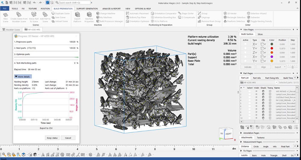
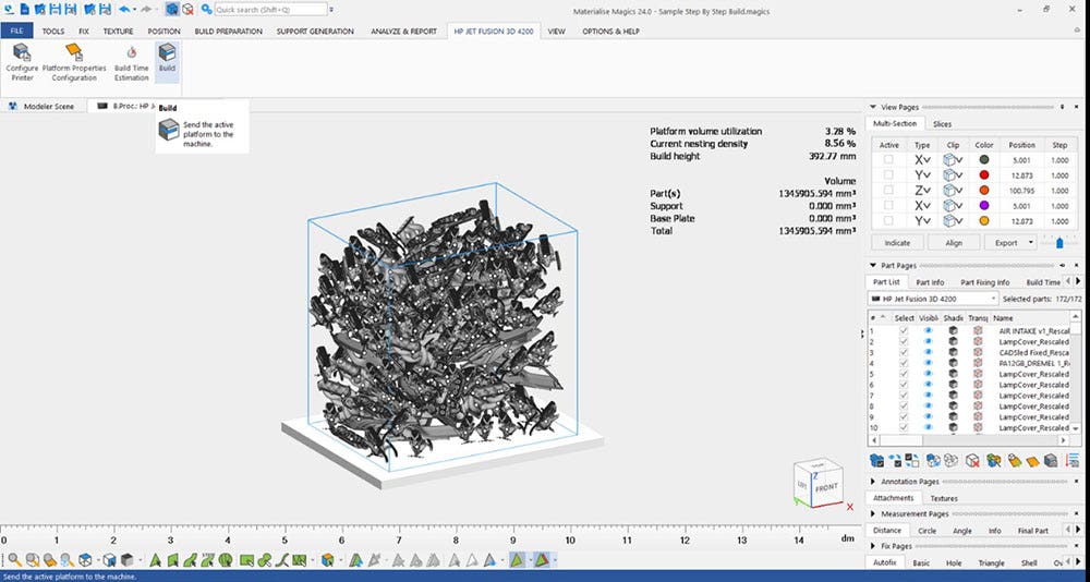
Our sample part for this example is a brake lever for a motorcycle. We will now take our sample brake lever and use Materialise Magics nesting to see how many can fit in the build volume of the HP MJF 4200 3D printer.
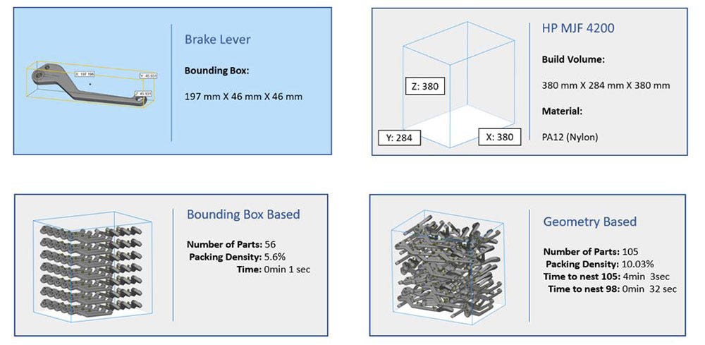
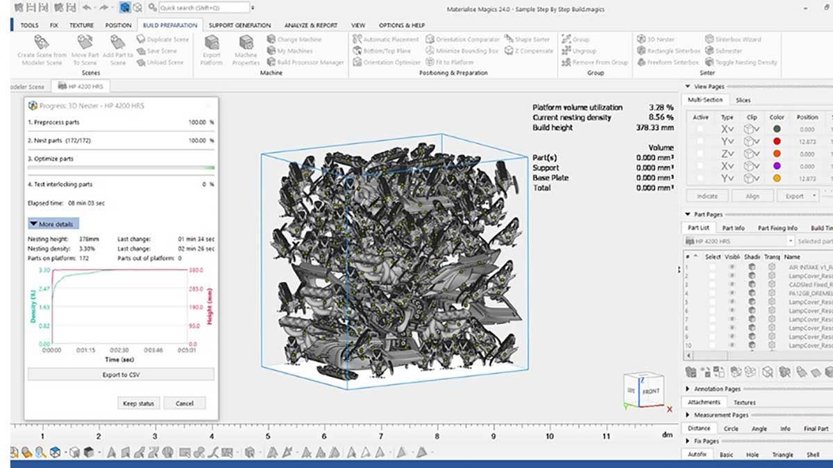
From the test builds above, we can see that geometry based nesting fit almost twice as many parts in a single build! For HP Jet Fusion, optimum packing density for powder reusability lies between eight and 12 percent. This tells us that our bounding box-based method is not getting the most of a single run at 5.6 percent. Normally when this happens with bounding box, I need to go back to the build and manually adjust parts and move them closer together in order to reach higher densities. Sometimes I can reach the eight percent minimum target, but many times this isn’t possible to do manually. The last thing you will notice is the time difference. Bounding box achieves almost instantaneous nesting while the geometry based nesting solution takes a few minutes. However, most of the parts in geometry based are nested fairly quickly (32 sec) and it is just those last few parts that take the bulk of the time. If you are manually adjusting parts after the bounding box scenario, you are sure to spend more time than the geometry based method would take anyways! Check out a video of how this process works here.
Comparing Part Cost and Production Output
Now we need to look at the most important differences between the two methods and that is part cost and production output. For HP systems we go back to that 8-12 percent packing density number for optimum performance and powder reusability. We can put a dollar amount on how important this is by looking at the cost analysis comparison below:
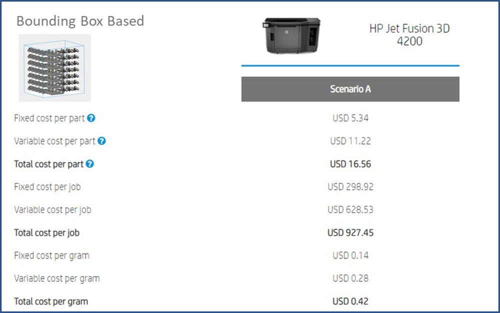
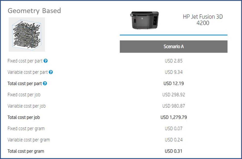
The results speak for themselves – $16.56 per part compared to $12.19 per part. Space this $4.37 price difference out over 105 parts and we save $458.85 in just one build! Not convinced yet? Now let’s run this scenario over the course of a year of builds.
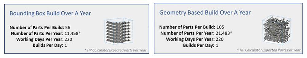
We can produce nearly double the amount of parts in a year by just using a different nesting software. This amounts to huge savings in time. Now let’s take a look at how much money can be saved over the course of a year:
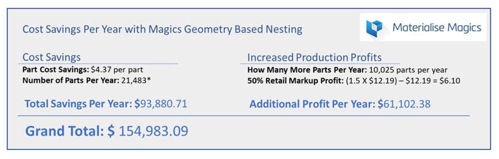
As you can tell, the cost savings and increased production are incredible through geometry based nesting with Materialise Magics. Now let’s dive into a typical workflow for nesting a build.
Nesting Features, Customization and Workflow
When working with powder-based 3D printers like the HP Jet Fusion printers, there are certain nesting guidelines and criteria that must be followed to achieve the best results. For example, here are some of the guidelines:
- Avoid any flat surfaces and angle horizontal surfaces 20 degrees or higher.
- Parts must be spaced at least 5mm apart.
- Fine details should face downward.
- Spacing between dense parts should be 10mm.
Here is how we can address these criteria in a typical workflow:
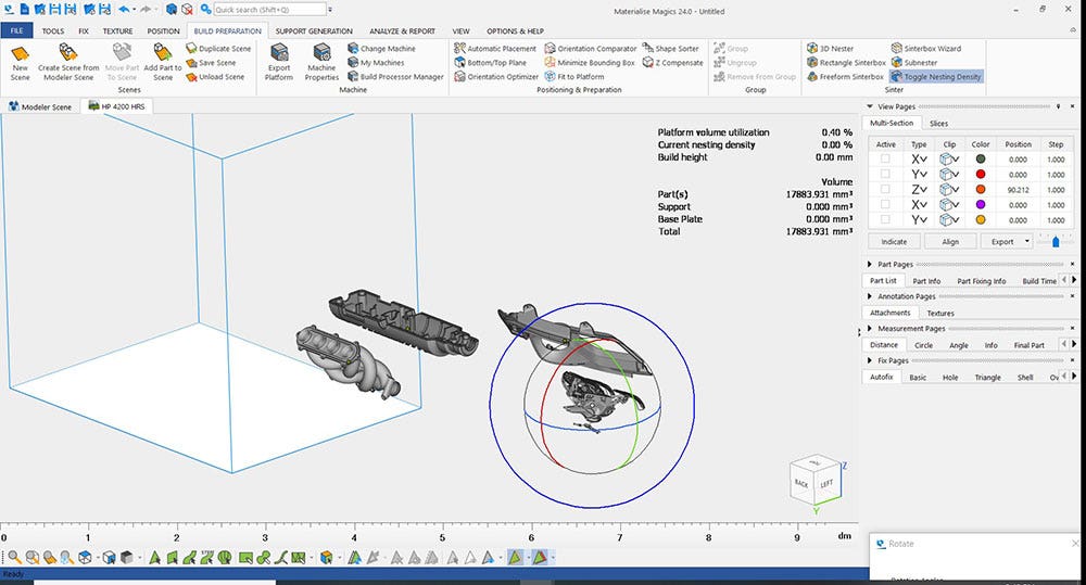
1. Import Models and Orient the Parts for Print
Materialise Magics accepts many different file types: STL, 3MF, VRML, Catia and SOLIDWORKS, just to name a few! This is where we orient parts in optimum print orientations.
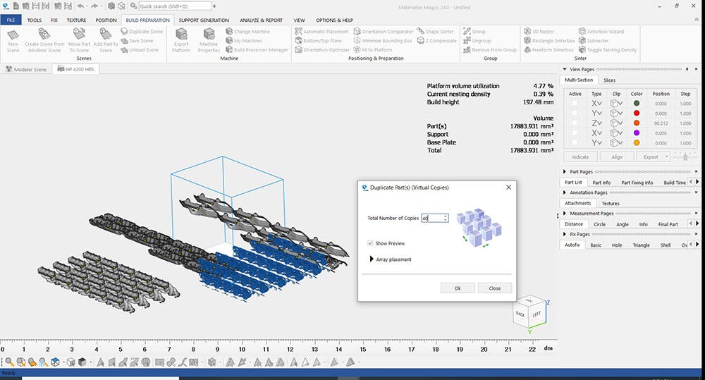
2. Duplicate the Quantities of Parts Desired for Each Build
Depending on your expectations for the part quantities, your strategy can change on part duplication. Sometimes you are working with assembly parts that need to be printed in consistent quantities. Or you may just want to maximize the amount of each part that can fit starting with the largest parts and then moving down to the smallest parts. Either workflow is easy to accommodate.
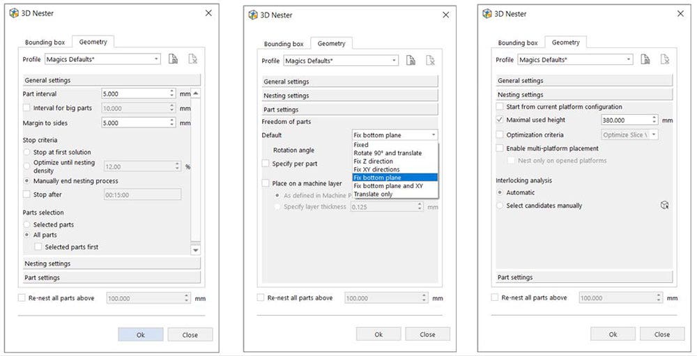
3. Configure Your Nesting Settings
At this point, we can select the nesting type: geometry or bounding box and then configure the constraints. Here, we can select part spacing and designate “Big Parts” to allow for extra clearance for large dense parts that are in the build with normal parts. “Freedom of parts” allows us to set limits on how the parts can move during the nesting process. In most cases, it is wise to keep the bottom plane constrained and allow for rotation of parts around the Z-axis when working with HP Jet Fusion technology. We can also toggle each part file and set custom “Freedom of parts” for each if necessary.
4. Start Nesting!
Depending on the complexity of the parts and your target nesting density, this can take on average about two to four minutes. If you are wanting to really maximize the build, you can let the nester run until you are ready for it to stop. The nester will continually add as many parts as possible and then seek to lower the build height has much as possible to decrease the print time.
5. Send the Job to Print
Materialise Magics has built-in plugins for many machines. HP machines plug right in, so it is easy to send jobs directly from Materialise Magics to your printer.
Slice Area Improvements with Geometry Based Nesting
The last thing I want to mention about geometry based nesting is how it compares to bounding box on a value known as “Slice Area.” This term relates to the amount of geometry cross-section on each layer. For HP Jet Fusion technology, print quality is improved with consistent slice areas between layers. This happens largely because a consistent slice area equates to consistent heat distribution between layers. Let’s take a look at our original two builds with brake levers and their slice area.
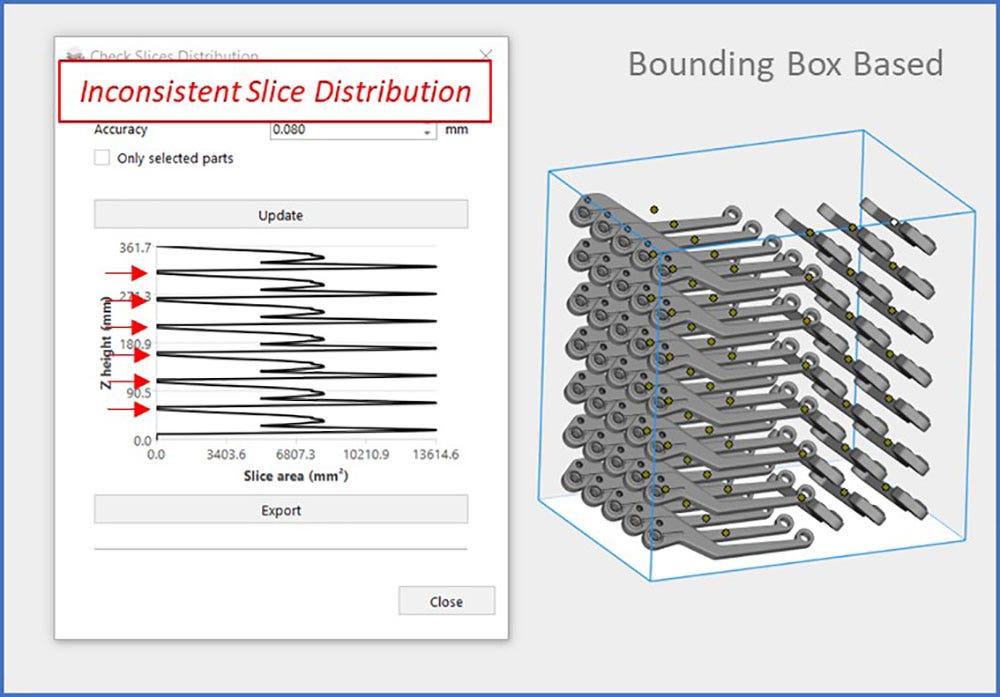
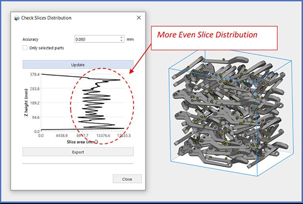
Geometry based nesting strategies have a much better slice distribution compared to bounding box. Bounding box can not overcome this challenge without manual editing. It is a good idea to keep the distribution curve as smooth as possible to have consistent heating between each layer of the build.
There you have it, we have looked at how to maximize nesting efficiency and bring down part cost with Materialise Magics and HP Jet Fusion 3D printing systems. In this blog, we have just scratched the surface of the tools available within Materialise Magics software. There are many more tools available, from STL editing to custom lattice structures. If you would like to see how Materialise Magics can save you time and money, feel free to contact us at Hawk Ridge Systems today!