A DXF or DWG file is the common input required for cutting machines like a laser, plasma, hot wire, or water jet cutters. Each machine is unique and likes the file formatted in a certain way to distinguish between operations like cutting, engraving, or etching. SOLIDWORKS gives you the option to map different entities (model edges, bend lines, sketches, form tools, etc.) to the required DXF or DWG formatting. You have the flexibility to change the line style and color for a variety of SOLIDWORKS entities.
Sheet Metal Part Example
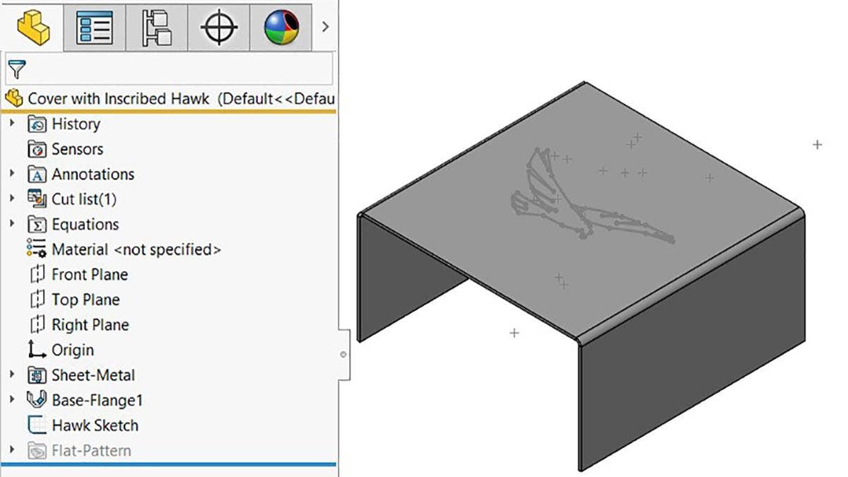
For this example, I want to create a DXF for this sheet metal part seen below where the model edges, hawk and bend lines all have different formatting. The hawk is going to be engraved, the bend lines will be etched, and the model geometry will be cut.
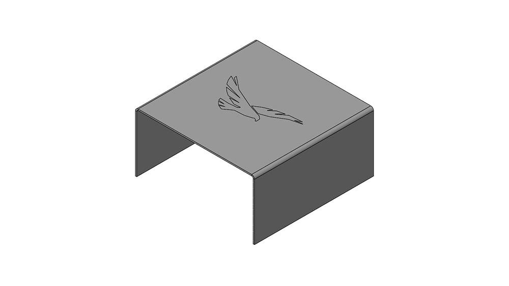
SOLIDWORKS sheet metal model to be used to generate a DXF with custom mapping.
In order to format the hawk to be engraved, the sketch containing the hawk must be a top-level feature in the FeatureManager Design Tree and not consumed by a feature. As you can see below, the hawk sketch is always visible and is not being used to generate a feature. In order to format bend lines, you must ensure the part file is a sheet metal part. This can be confirmed when you have the Sheet-Metal folder in the Feature Tree as seen below. For more information on creating and using sheet metal parts in SOLIDWORKS, our Hawk Ridge Systems training class provides all the answers.
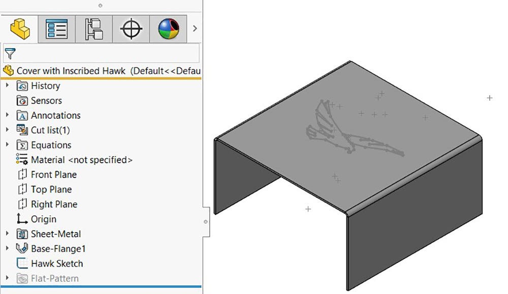
Feature tree of the sheet metal part displaying the sheet metal folder and sketch in the top level of the tree.
Required System Options
To customize or Custom Map SOLIDWORKS to DXF/DWG, you need to turn a System Option on. You can access the System Options from the gear icon at the top of the SOLIDWORKS screen. Then, you need to select Export in the left column and click the Enable checkbox under Custom Map SOLIDWORKS to DXF/DWG as seen in the image below. Access this option from the Save As window by hitting the Options… button as shown below.
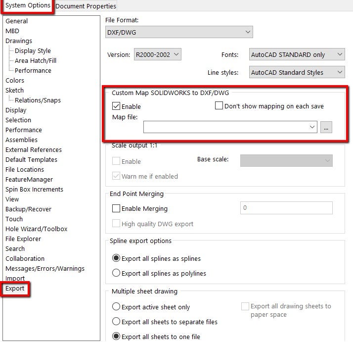
Export section of the system options highlighting the custom mapping section.
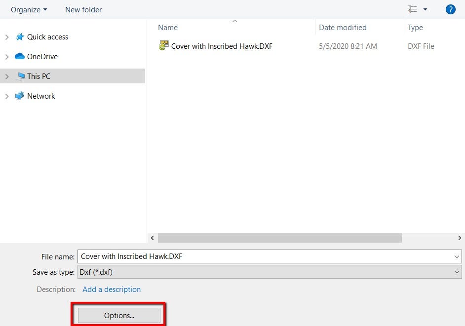
Save as window highlighting an options button to direct you to the DXF export options.
DXF/DWG Output
The next step is to export the flat pattern as a DXF or DWG. This can be done by right-clicking on the face of a sheet metal body and selecting Export to DXF/DWG, or you can do a Save As command and change the Save As type to DXF or DWG. Both those workflows will display the DXF/DWG Output window shown below. In the Export section of the property manager, select Sheet Metal. This will give you the option to export geometry, bend lines, forming tools, sketches and everything else listed in the property manager. Since I want to format my Geometry, Bend lines and Sketches, those boxes need to be checked before continuing.
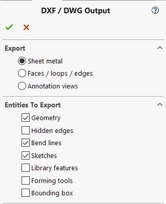
DXF/DWG output property manager.
Mapping and Defining Layers
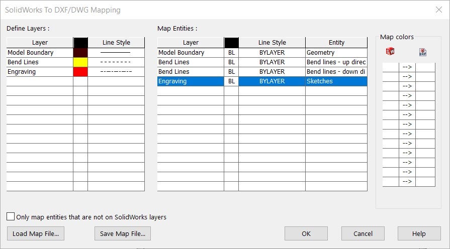
After accepting the DXF/DWG Output you will be prompted with the SOLIDWORKS to DXF/DWG Mapping window if you have the appropriate options selected. This window is where you can define your DXF or DWG layers, that layer’s formatting, and what SOLIDWORKS entity you want to map to each layer. The Define Layers section is for the DXF file. The first column Layer is for naming the layer in the DXF file.
For this example, I have made a layer for the model boundary, Bend Lines and Engraving. The second column in the Layer section is for the color you want that layer to appear in the DXF or DWG file. Finally, the last column in that section is the Line Style, this is how your line will be formatted in the DXF or DWG file. There is a long list of line styles to choose from, but I made my model edges a solid line, the bend lines a dashed line, and the engraving a short dash to long dash line. These were a random selection to display the functionality and your choice will depend entirely on your machine. You can also use this mapping to just generate layers in the DXF or DWG and keep all the lines solid and black but in a different layer.
SOLIDWORKS to DXF/DWG mapping window.
The Map Entitles section is where the relationship between the SOLIDWORKS file and the exported file is established. The Layer column in the Map Entitles section is defining what DXF or DWG layer you would like the SOLIDWORKS entity to be written to. The next two columns are where you can redefine the color and Line Style of the layer but the “BL,” or “BYLAYER” means that the formatting of the line in the Define Layers section will be used.
The last Entity column is where you select the SOLIDWORKS entity you want to map to the selected Layer. As you can see in the figure above, the SOLIDWORKS Geometry, or model edges and cut-outs are mapped to the “Model Boundary” layer. The SOLIDWORKS Sketches are mapped to the “Engraving” layer and the bend lines are mapped to the “Bend Lines” layer.
Once you are happy with this mapping you can Save Map File to make this process simple if you have multiple machines with unique inputs, jobs that require different formatting, or clients that like specific formatting. You can Load Map File and the data input is done for you. Clicking the OK button will save the DXF or DWG. You can see the results of this specific export in the image below.
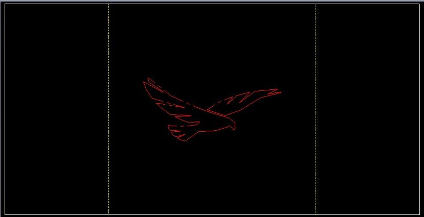
DXF file with custom layer and format mapping for SOLIDWORKS.
Check out our website for more information on SOLIDWORKS, and if you have any questions be sure to contact us at Hawk Ridge Systems today. Thanks for reading!
