Have you ever manufactured a part only to find it doesn’t fit properly in an assembly? Or perhaps you’ve completed an assembly only to discover that components don’t have adequate range of motion for proper function. It happens to the best of us, and you likely already know how frustrating the lost time and money from ill-fitting components can be. Fortunately for us, SOLIDWORKS provides several tools for checking the form, fit and function of assembly components prior to manufacturing, helping you avoid design rework and heartache. In this article, we cover three of the most important strategies in this tool set: Visual Inspection, Interference Detection and Collision Detection, using this 1950s-style retro refrigerator design:
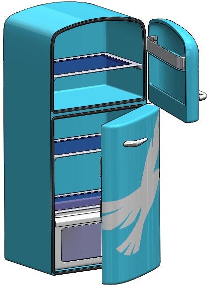
Hawk Ridge Retro Refrigerator Assembly
Look for Obvious Interferences Using Graphical Techniques
Major interferences are often easy to spot with a simple visual inspection of the model. Using the default “Shaded with Edges” Display Style, be on the lookout for missing edges between components where you expect edges to be. Additionally, if you’re using a variety of colors in your model, you may notice different colors bleeding through one another in a funny-looking pattern. Both of these symptoms typically indicate interference between components, and in many cases don’t require any special tools to identify. In the example below, both cases can be seen:
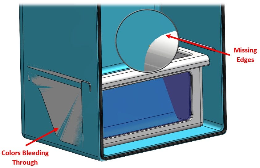
Identifying Interference Using “Shaded with Edges” Display Style
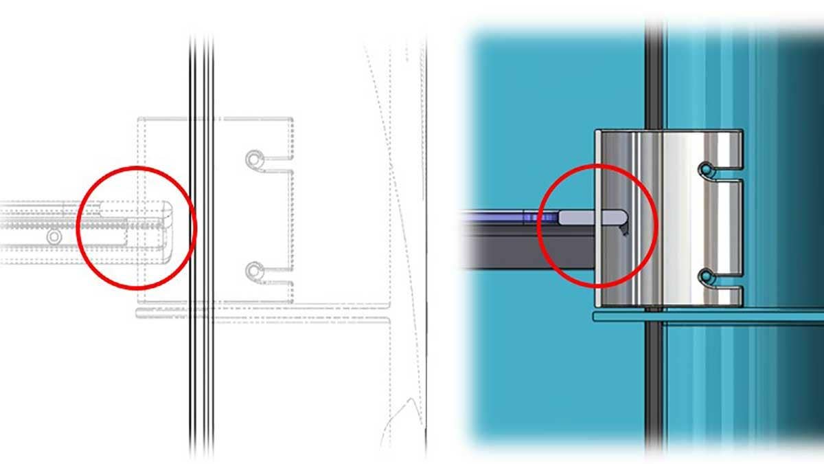
Additionally, you may consider switching the Display Style to “Hidden Lines Visible” or taking a Section View to visually check for interferences that may be otherwise obscured in the Shaded with Edges Display Style. In the example below, we can clearly see interference between shelves when the fridge is in a closed position. Because these components only interfere in the closed position, they would be impossible to see without a Section View or alternate Display Style:
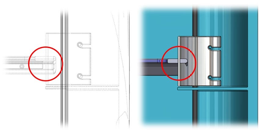
Identifying Interference with “Hidden Lines Visible” Display Style (Left) and Section View (Right)
Visual inspection is a great first-pass analysis for finding interferences, but in many cases, small instances of interference may still sneak by, and even the tiniest interference can be the difference between a product that works, and a product that goes in the trash.
Use Interference Detection in Important Assembly Positions
The Interference Detection tool is indispensable when it comes to finding component interference, especially when they are small, or when you’re working with a large assembly. To activate it, access the Evaluate tab in the CommandManager and click Interference Detection. The resulting PropertyManager is shown below, and has several options:
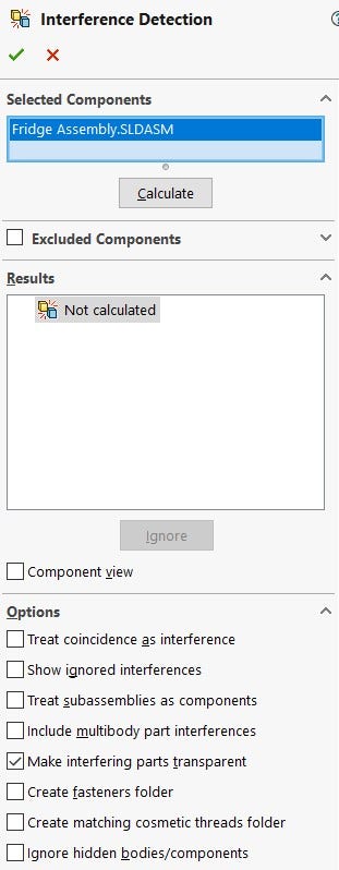
Interference Detection PropertyManager
Many of these options are self-explanatory, but some of them may require a bit of clarification. For example:
Treat Subassemblies as Components: Views subassemblies as single components so interferences between a subassembly’s components are not reported.
Create Fasteners Folder: Under Results, segregates interferences between fasteners (such as a nut and bolt) into a separate folder named Fasteners. (These interferences are generally ignored)
Remember, for many PropertyManagers (including Interference Detection), the SOLIDWORKS help file can be accessed by clicking the icon at the top-right of the menu. This can be very helpful for understanding the available options.
If you don’t have anything pre-selected when initiating Interference Detection, the whole assembly will be analyzed by default. This is great for small to medium assemblies, but for larger assemblies it’s best practice to clear the assembly from the “Selected Components” window and choose a few that you’re interested in for faster performance. Once you’ve chosen your components (if desired) and set the proper options, simply click Calculate and watch as SOLIDWORKS does the heavy lifting for you.
Results will be displayed and highlighted in red upon selection, giving you all the information you need to make adjustments to your design for the perfect fit. I always recommend at least two iterations of Interference Detection as design adjustments are being made to ensure design changes haven’t resulted in new interferences. Intentional or inconsequential interferences may also be selectively disregarded by clicking the Ignore button. It looks like we may be in a bit of trouble with the fridge design!
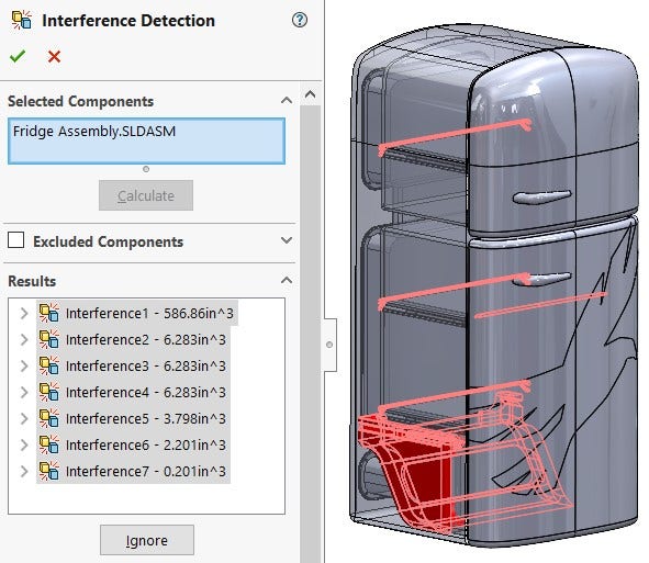
Instances of Interference in the Refrigerator Assembly via Interference Detection
Fortunately for us, most of these interferences can be fixed with simple changes to mates and component dimensions. For assemblies that include some form of motion, however, there may still be instances of interference that go undetected. When assemblies include moving parts, it’s necessary to look for interferences throughout the range of motion of components. For this task, the static “fixed position” nature of Interference Detection won’t quite cut it (unless you feel like performing a hundred iterations at different component positions and hoping for the best … I didn’t think so).
Use Collision Detection to Check for Interferences
This step is unnecessary for assemblies that aren’t intended to have any moving parts, but is absolutely critical for those that do. Interferences often go undetected because they only reveal themselves in very specific positions, often somewhere between “open” and “closed” positions. Collision Detection can solve this issue for us by dynamically checking for contact as a component moves through space. This tool can also be used as a general check for total range of motion. In this example, we’ll check to see if there are any issues when trying to shut our fridge doors, and also figure out how far they can open.
First things first though, the Collision Detection tool does not have its own dedicated command. You will not find it on the CommandManager or drop down menus because it’s actually an option that must be enabled in the Move Component command. To use Collision Detection, navigate to the Assembly tab of the CommandManager and select Move Component command. From here, ensure that the Collision Detection option is enabled in the PropertyManager:
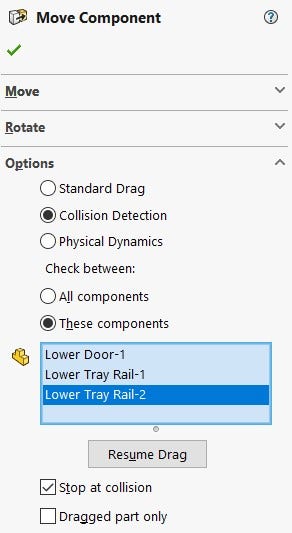
Move Component PropertyManager with Collision Detection Enabled
Like Interference Detection, there are a handful of options worth considering. By default, collisions between all components will be considered. This may work well for smaller assemblies, but even medium-size assemblies will likely require selection of “These Components” in order to limit the scope of Collision Detection and improve performance. To use “These Components,” turn on the option, select the components you’d like to analyze, then click “Resume Drag” to continue. Then, to check for collisions, click and drag components throughout their range of motion. By default, components will stop moving once a collision has been detected, and the colliding faces will highlight as shown below (you may need to hide components before using Collision Detection to clearly see what’s happening):
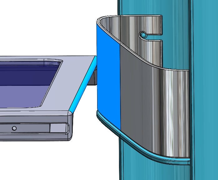
Components Colliding on Movement as Shown through Collision Detection
As you can imagine, Collision Detection is extremely helpful for finding interferences that may otherwise go unnoticed if an assembly is only analyzed in specific positions. Pro tip: you can even attach reference dimensions to model geometry and use Collision Detection to quantify range of motion in exact values! Here, I discovered that my upper door opens to 179.94 degrees. Good enough!
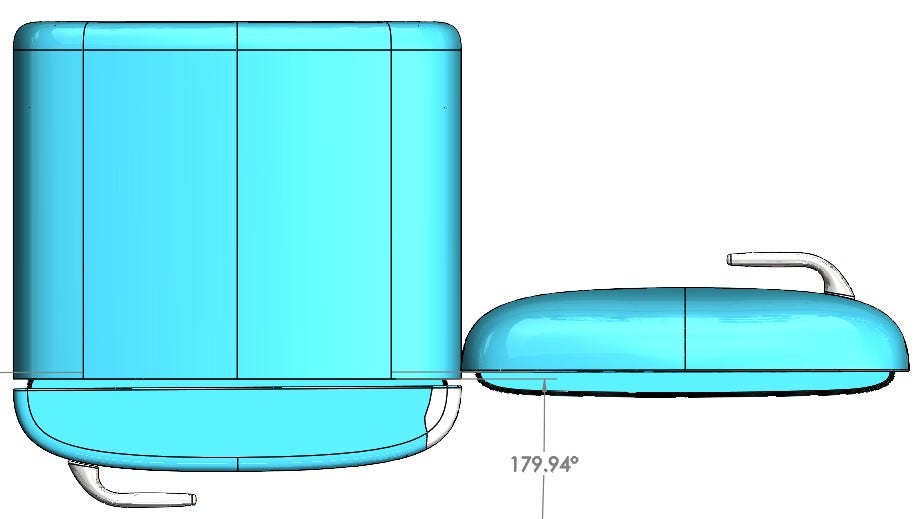
Combining Collision Detection and Reference Dimensions to Quantify Range of Motion
To be absolutely sure of the form, fit and function of your assembly components, all three of the tools discussed here should be employed regularly (at least if your assemblies include motion). Begin with a visual inspection, looking for missing edges, bleeding colors and obvious interferences. Follow up with Interference Detection in important assembly positions, and if motion is a concern, finish up by using Collision Detection throughout the range of motion. With these three tools in your utility belt, you can rest easy knowing that if it doesn’t fit, at least it’s not your fault!
Do you have any additional tips or tricks for making sure assembly components fit together properly? Let us know in the comments! For more information on SOLIDWORKS or if you have any questions, contact us at Hawk Ridge Systems today. Thanks for reading!


