
Every year, Hawk Ridge Systems offers live launch events for its customers to introduce the new enhancements of that year’s release. What if you were unable to make one of the 2018 live sessions? Don’t worry – we have you covered! We recorded the live stream of our first Launch Event for 2018, and separated them into 8 modules so you can easily digest What’s New in 2018! Even if you’ve attended a launch in another city (besides Palo Alto, where this one was recorded), it’ll be different and exciting content! In today’s blog article, we’ll continue wrapping up Module 3, diving into some of the enhancements to assemblies and 3D Interconnect! Here are some of my favorites:
Linear Component with Rotation
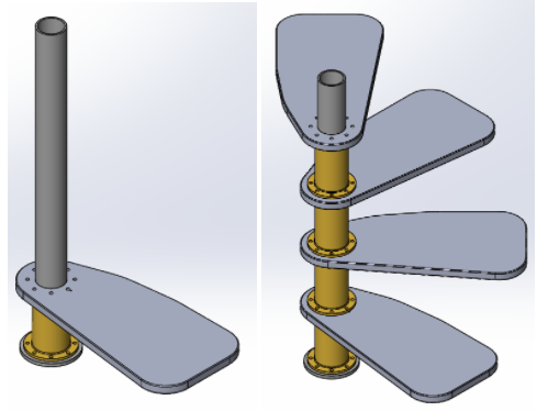
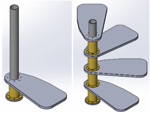
Do you remember this example from the Assembly Modeling class? How did we achieve that result? We used Copy with Mates, selecting the component(s) we want to copy, and then selecting the mates we want to apply to our new components. In 2018, there’s another way to accomplish the same task – Linear pattern with rotation! This alternate method can be accomplished by going to:
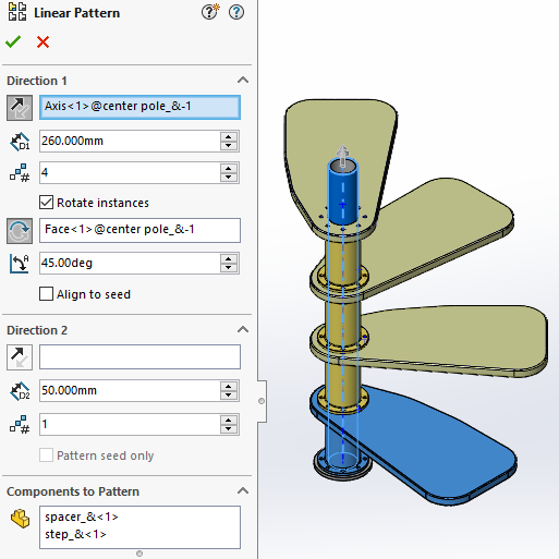
- Linear Component Pattern and first selecting the direction we want to pattern (we chose the temporary axis, in this case)
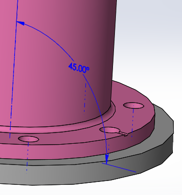
- Specifying spacing, instances, axis of rotation (we choose the face, here), and angle.
- Afterwards, we can specify which component(s) we will be patterning and if we’d like to skip any instances.
What’s the difference between doing it this way? It depends on the information provided and our goal. If we know the rotation angle and need to be able to adjust it easily, linear component pattern with rotation could be easier because we can double click the angle to modify it. With Copy with Mates, you don’t need to know the angle, just the face it’s being mated to.
In terms of our goal, if we had needed to create many more instances, I can see how the Linear Component Pattern with Rotation would be much faster than Copy with Mates. With that said, keep in mind that when we do a Linear Component Pattern, the components are fixed, as opposed to mated if done with Copy with Mates. If we were to dissolve the components, they would then become underdefined. The wonderful thing is we now have options! For more examples and information regarding this feature, register for Module 3 and Nikki Stakic’s blog on Rotate Linear Pattern here!
Mating Enhancements
Magnetic Mates
- In 2017, SOLIDWORKS introduced Magnetic Mates that help with easily assembling facility layout components by dragging and dropping the assets into the top-level assembly.
- In 2018, we now have more functionality such as:
- Cycling through connection points, by using the left bracket ([) to cycle through connection points on the moving component and the right bracket (]) to cycle through connection points on the static component.
- Defining multiple ground planes.
- Locking/unlocking magnetic mates quickly with the Lock mate (
 ) icon near the cursor
Temporarily hide faces with the ALT key
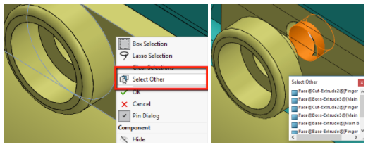
- Before, in the mate menu, we had to right click > Select Other to select through faces. To continue hiding faces and getting to our desired selection, we’d continue right-clicking the faces we didn’t need or chose from the Select Other selection window.
-
- In 2018, that process has be streamlined to just one keyboard button: the ALT key. Now, when in the mate menu, we can temporarily hide faces by hovering over the face and just clicking the ALT key.
Misaligned concentric mate
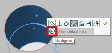
- In 2018, SOLIDWORKS now gives the engineer the ability to create misaligned concentric mates. To begin, we’ll create a concentric mate on 1 pair of holes. If we then move onto a 2nd pair of holes and we find that they are misaligned – we can either Edit the Part in the assembly and fix misalignment or create a misaligned concentric mate.
-
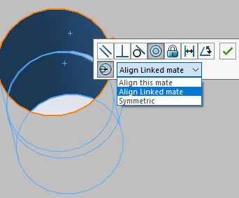
- If we leave the parts unedited, and select Concentric Mate, we’ll be given the option to turn on the Misaligned mate. Once enabled, the dropdown will provide us with 3 options:
- Align this mate: it makes the selected 2 holes concentric and misaligns the other set.
- Align Linked Mate: it makes the selected 2 holes misaligned, and the other set concentric.
- Symmetric: the offset is equally applied to both sets of mated holes.
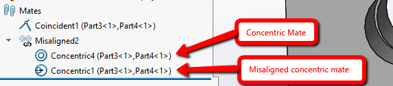
- Additionally, we can also specify an allowed tolerance – which will display an error if that amount is exceeded.
- After the mates have been created, they can be found under Mates in the FeatureManager.
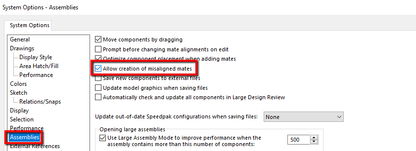
- If we don’t want to allow misaligned mates, we can uncheck it by going to System Options > Assemblies > Allow creation of misaligned mates.
Other Assembly Enhancements
Update SpeedPak Configurations Automatically
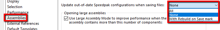
- There is now an System Option called ‘Update out-of-date Speedpak configurations when saving files” for top level assemblies. We can find it by going to Tools > Options > System Options > Assemblies
- When doing so, we’re provided with 3 options:
- All, which will update all out-of-date SpeedPak configurations
- None, which will not update any out-of-date SpeedPak configurations
- With Rebuild on Save Mark, which will update all out-of-date SpeedPak configurations that have a Rebuild on Save Mark. This can be done either in the ConfigurationManager or the SpeedPak PropertyManager
Smart Exploded Lines
- Explode Lines can be automatically added to exploded views by right-clicking the explode view > Smart Explode Lines.
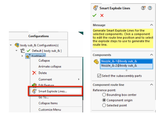
- From here, we can select the components we’re creating explode lines for and then determine the reference points for the explode lines:
- Bounding box center – locates the explode line relative to the bounding box center of the selected component
- Component origin – locates the explode line relative to the origin of the selected component
- Selected point – locates the explode line relative to the selected point.
- Most importantly, these explode lines really are intelligent as they’ll update if explode positions change!


3D Interconnect
- SOLIDWORKS 3D Interconnect has helped users streamline collaboration between their vendors, by allowing them to bring CAD data from AutoDesk Inventor, PTC Creo, CATIA V5, etc.
- In SOLIDWORKS 2018, 3D Interconnect now works with neutral files, such as STEP, IGES, and ACIS!
- In addition, it can also read reference planes, user defined attributes, or custom properties from these neutral formats.
- Lastly, additional information supported for 3rd party files include:
- Assembly cut features from PTC Creo and UG files.
- Custom Properties from ACIS, AutoDesk Inventor, CATIA V5, IGES, PTC Creo, Solid Edge, STEP, and UG files.
- Material Properties, such as material name and density attributes.
- Unconsumed Sketches and Curves
- Reference Axis from CATIA V5 Files
For more information on exactly how this is done, Sean Marrs created an excellent blog and video that can be found here! Want to see some of these assembly enhancements in action? Register for the recorded Live Stream and look at Module 3 where we go into more detail! Stay tuned for the next blog in the series where we’ll dive into Module 4! For more information, request a SOLIDWORKS 3D CAD quote or contact us at Hawk Ridge Systems today. Thanks for reading!


