 If there’s one thing I’ve learned from immersing myself in simulation tools
for the last several years, it’s that the phrase “work smarter, not harder” is
a pretty good advice. Of course, working hard is always admirable – but using
our brains can make that hard work go a lot further. I think the maxim applies
especially well to any kind of simulation, where the hard work is being done
by your computer’s CPU (and it of course can only do so much).
SOLIDWORKS
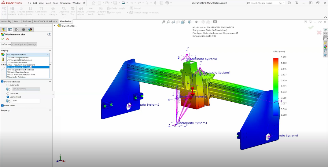
has always taken this philosophy to heart, particularly with
SOLIDWORKS Flow Simulation, the embedded CFD analysis tool. Flow Simulation utilizes a number of
technologies to ensure that a simulation is both easy for the user to set up
and also gives accurate results in a wide range of problems – for example, the
ability to detect either laminar or turbulent flow, analyze compressible
fluids, and resolve complex geometry easily.
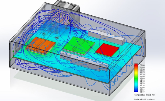
One example of this mantra is in apparent in
electronics cooling
problems, which is one of the most common applications of Flow Simulation.
When defining this kind of simulation, users typically needs to put in some
known inlet or outlet conditions – like for fans or vents in the case.
Oftentimes it may seem simple enough to look at a fan’s rating, say 35 CFM,
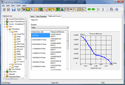
and type that in as a volume flow rate. The problem, as any fan designer will
tell you, is that this output isn’t always the same. The volume flow rate of a
fan (or a pump for that matter) depends on the pressure gradient across it,
and this relationship is generally shown as a curve. If your fan is trying to
push air into a small, crowded box where pressure is building up, the curve
will tell you how much its performance is being reduced. If you were trying to
enter the flow rate manually, the only way to get it right would be to
repeatedly guess-and-check, re-running the simulation until the flow rate
matches the pressures in the results.
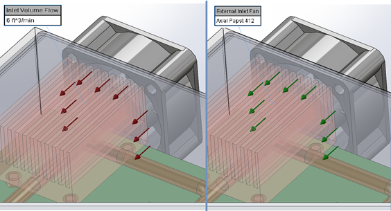
Luckily, in SOLIDWORKS Flow Simulation, users can directly specify these fan
curves to an inlet or outlet using the Fan condition, which can make a big
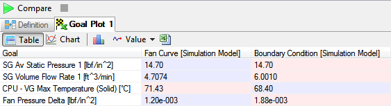
difference in the realism of a simulation. For example, take a look at the two
different cases of a desktop computer using Flow Simulation’s Compare Results
tool. In one, the maximum CFM rating of the fan is entered as an inlet
condition; in the other, the proper fan curve is applied. As it turns out, due
to the pressure buildup in the box, the fan is blowing less air in than you
might expect- about 4.7 CFM instead of the rated 6 – resulting in a higher CPU
temperature. If you’re trying to size heat sink fins or optimize fan
placement, that difference might be the key to getting the right answer.
Best of all, SOLIDWORKS Flow Simulation has a library of real fan curves
built-in to the Engineering Database, which can be expanded with the
Electronics Cooling add-on module to include manufacturers like Delta, Sanyo,
and Mechatronics. Of course, you can always create your own fan curves as
well.
So, remember the old saying, and give your simulation the setup conditions it
needs to work smarter. Your CPU will appreciate the menial labor you’ve saved
it- and your boss might, too.
Want to learn more about SOLIDWORKS Night School? Read Simulation Product
Manager
Glenn Whyte’s Night School blog.