Anyone who has used
SolidWorks Simulation
for some time probably knows about the Design Study functionality, and maybe
even the Optimization functionality found in
Simulation Professional. Users of
Flow Simulation
have been asking for similar functionality, but all we had to work with was a
single-parameter optimization study. I can finally say that now with
SolidWorks Flow Simulation 2013, we can run multiple what-if scenarios while
changing multiple variables!
I was helping a colleague of mine with a Flow Simulation project when I was
first exposed to the new parametric study in 2013. I was helping to create a
custom Porous Media within the Engineering Database, but I needed some input
data like a graph of Pressure Drop vs. Flow Rate:

How was I going to accomplish this? SolidWorks 2013 Flow Simulation Parametric
Study to the rescue!
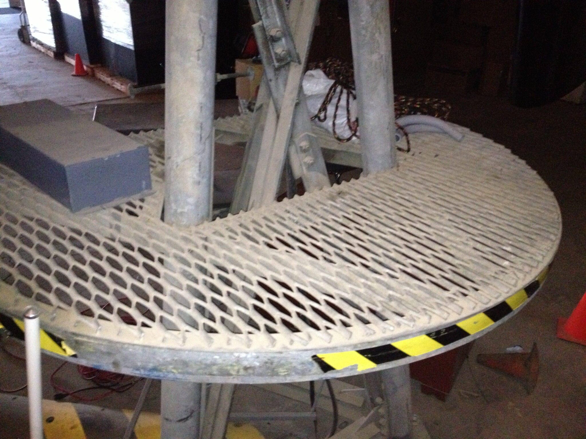
This was the customer’s example:

To make dimensions easier, I modeled this in SolidWorks:

Before I ran this study, I wanted to take a look at this mesh to make sure it
was adequate. In particular, I wanted to make sure that the mesh captured the
details of the grating that I modeled. I started with the initial mesh slider
at “3”. At first glance, it looked as though the perforations were captured:

One thing to be careful about though; the option to “Use CAD Geometry” is
turned on by default in the cut plot properties and can be deceiving. This is
what my mesh really looked like:

Definitely not what I was expecting! The recommendation is to have “Use CAD
Geometry” option turned off.
I needed to refine my mesh, either using the automatic settings (the slider
bar) or manual mesh refinement. I opted to use the manual mesh refinement and
increase the “small solid feature refinement” level to 3.

Much better! I knew I needed to run several studies, each time increasing the
volume flow rate and monitoring the pressure drop across the perforated plate.
Until 2013, the only way to do this was to manually change the inlet boundary
condition and rerun. With the release of SolidWorks Flow Simulation 2013, I
could now use the updated Parametric Study tool! I used the “What-If” setting;
there is also a “Goal Optimization” which works similar to past versions.
I chose which variable I wanted to change (this can be either a flow parameter
or a dimension) and what values to use, which goal(s) I wanted to monitor, and
then ran it.
 Parametric study results exported to Excel.
You can export your results to Excel; I had this as my final output:

My colleague used the raw data for his Porous Media definition and he was good
to go. As you can see, the new Parametric Study in SolidWorks Flow Simulation
2013 opens up new possibilities, many of which were available to people using
Design Studies in SolidWorks Simulation. Whether you are trying to optimize
pipe length or being lazy and batch running multiple what-if scenarios, the
new 2013 Parametric Study is the way to go!